
Case Modification - Stereo VU Meter
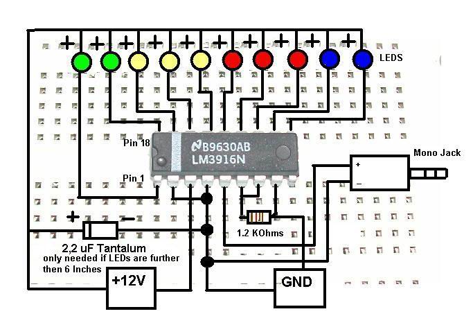
The stereo VU meter circuit using the LM3915/LM3916 ICs is a practical project that allows for visual representation of audio signal levels. The LM3916, in particular, is well-suited for this application due to its ability to drive multiple display elements simultaneously, providing an intuitive and engaging way to monitor audio levels.
To construct the circuit, begin by gathering the necessary components, which include the LM3916 IC, 10 LEDs (or an equivalent display type), a 2.2 µF tantalum capacitor (if required), resistors for current limiting, and a suitable power supply. The circuit operates by connecting the audio signal to the input pin of the LM3916, which processes the analog voltage levels and activates the corresponding number of LEDs based on the input signal strength.
When prototyping on a breadboard, it is essential to ensure that all connections are secure and that the power supply is correctly configured. The arrangement of the components can be customized to fit the desired aesthetic or functional requirements. Once the prototype is tested and verified, a permanent circuit layout can be designed, taking into consideration factors such as wire lengths and connector types. DUBOX connectors are particularly useful for making modular connections, allowing for easy adjustments or replacements of LEDs.
In summary, the LM3916-based stereo VU meter provides an excellent opportunity for both learning and practical application in electronics. With careful planning and execution, this project can yield a functional and visually appealing audio level indicator.This is a quick how-to guide for making a stereo VU meter using the LM3915/LM3916. The LM 3916 is an integrated circuit (IC) that takes analog voltage levels and drives 10 LEDs, LCDs, or vacuum fluorescent displays to represent digital voltage levels just like a VU meter. The 2. 2 uF Tantalum Capacitor is only needed if your wires from the IC to t he LEDs are longer than 6 inches. Although the specs for the LM3916 say you can use any voltage from 3 V to 20 V, I suggest using at least 12 V to power your circuit. So before soldering everything together, let`s just test the circuit on a protoboard. First let`s get everything ready. The following items are what we need for this project: After getting all the components ready, it is time to start prototyping.
First to be placed onto the protoboard is the most important piece, the LM3916 IC. Now it`s time to design the permanent circuit. Here is where you can get creative, you can arrange them the way you want them, and find creative ways to put it all together. Here is howI did mine. I used DUBOX connectors (those blue things you see in the picture). By using those connectors I could just use the wires you see in the next picture (hanging from the power supply) to change LED color or simply making longer or shorter wires to reach my LEDs.
🔗 External reference
Related Circuits
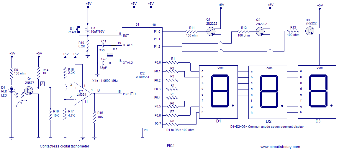
A three-digit contactless digital tachometer utilizing an 8051 microcontroller is presented for measuring the revolutions per second of rotating objects such as wheels, discs, or shafts. The tachometer can measure up to a maximum of 255 revolutions per second...
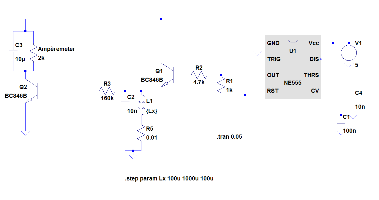
The objective of the project is to construct a simple, low-cost inductance meter. The primary components of the project include an IC 555, a transistor, a resistor, and a capacitor. The inductance meter designed in this project utilizes the IC...
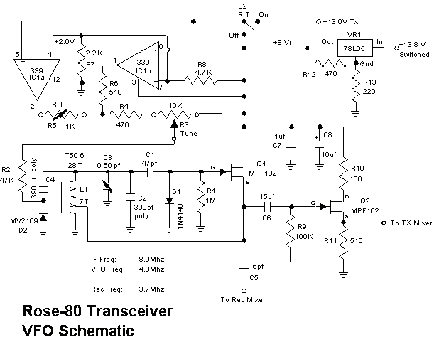
1. Full 5 watt output using a power MOSFET final that is resistant to high SWR and thermal runaway. This final is very efficient and runs much cooler than traditional bipolar designs. 2. Highly sensitive and selective superhetrodyne receiver...
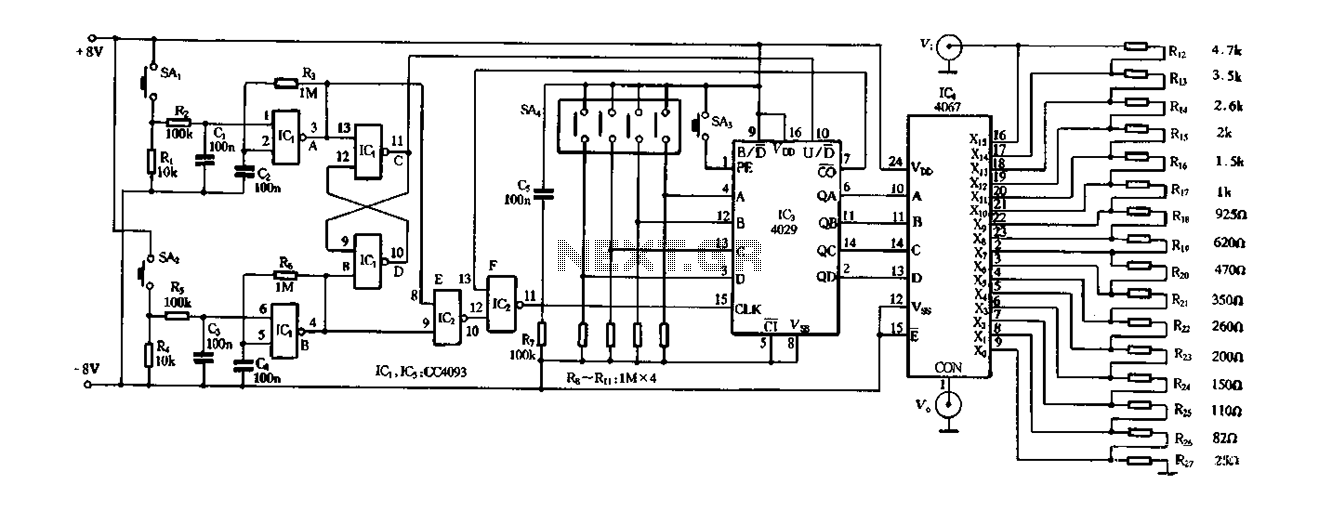
Figure 4-14 illustrates a digital integrated circuit featuring 16 preset potentiometers for Siniperca electronic circuits. The circuit comprises three main components: an input controller, a presettable counter, an analog electronic switch, and a resistor network. It includes a push-button...
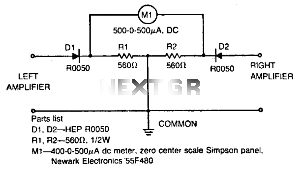
The meter displays the volume and tone control balance between the left and right stereo amplifiers. For enhanced usability, the meter is designed as a zero-center type. Resistors used in the circuit have a tolerance of five percent or...
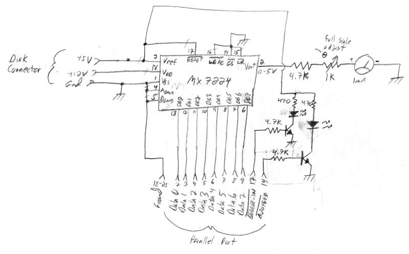
The meter was acquired from eBay and features a full-scale movement of 1 mA, already marked from 0 to 100. The original scale was removed, scanned, and modified to include "% NETWORK" markings using an image editor. The new...