
9V Power Supply For Garage Shed Alarm
The 9V power supply circuit for the garage shed alarm is designed to provide a stable voltage source for the operation of the alarm system. This circuit typically consists of a transformer, a rectifier, and a voltage regulator to ensure that the output voltage remains constant at 9 volts, even with variations in input voltage or load conditions.
The transformer steps down the AC mains voltage to a lower AC voltage suitable for the rectification process. Following this, the rectifier converts the AC voltage to pulsating DC voltage. A smoothing capacitor is often included in the circuit to reduce the ripple in the DC output, providing a more stable voltage level.
To ensure the output voltage does not exceed 9V, a voltage regulator is integrated into the circuit. This component maintains the output voltage at a fixed level, regardless of fluctuations in input voltage or load current. The regulator may be a linear type, such as the 7809 voltage regulator, which is commonly used for such applications.
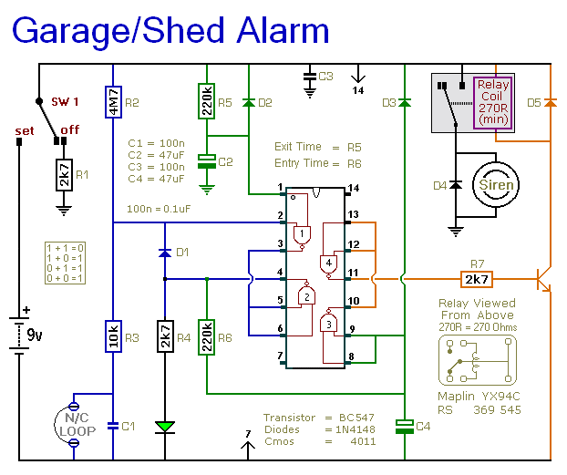
The alarm circuit itself is designed as a single-zone burglar alarm, meaning it monitors a single area for unauthorized entry. It typically includes a motion detector or door/window sensors that trigger the alarm when an intruder is detected. The alarm may be an audible siren or a visual indicator, such as flashing lights, to alert the owner of a breach.
In summary, this circuit combines a reliable 9V power supply with a single-zone burglar alarm system, making it suitable for use in a garage shed or similar environments, ensuring both security and functionality.The following circuit shows about 9V Power Supply For Garage Shed Alarm Circuit Diagram. Features:single-zone burglar alarm circuit, used with the .. 🔗 External reference
Related Circuits
This regulated power supply was built as a simplified outboard version of a PSU in my first phono stage. Replacing hexfreds with tube rectifier eliminates the need for power-on sequencing. Chassis (salvaged from a hospital laser PSU) size is...
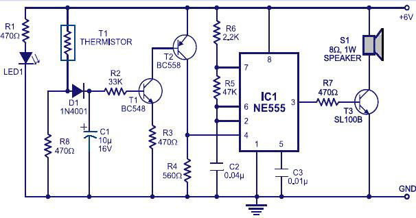
Various fire alarm circuits are discussed, featuring a new design that utilizes a thermistor and a timer. This circuit is straightforward and can be easily implemented. The thermistor exhibits low resistance at high temperatures and high resistance at low...
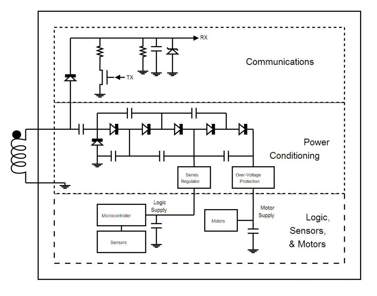
Wireless power transfer is not a new concept; it has been discussed since Tesla's patent in 1900, titled "Apparatus for Transmission of Electrical Energy" (USPTO #649, 621). As the technology evolves, the range of potential applications will expand. For...
This circuit is a dual voltage regulated power supply, +12, -12, 0 volt. It uses the 7812 and 7912 regulators. You need a 18VCT, 1A transformer at input. More: Caution: Input / Ground are reversed between the 7812 and...

The transformer has two primary windings and six secondary windings; the two 120-VAC primary windings and the 6.3-VAC secondary windings are connected in parallel. Modules A and B are identical; therefore, only the components of Module A are specified....
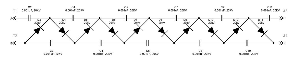
The Cockcroft-Walton multiplier employs a series of diodes and capacitors arranged in a cascade to generate a high-voltage DC potential from an AC input. This circuit topology utilizes diodes to charge capacitors in parallel and discharge them in series....