
A 40 meter QRP - Transceiver
The transceiver circuit described is a fundamental design that combines both transmitter and receiver functionalities, typically utilized in amateur radio applications. The circuit operates within a specified frequency range, often adjustable via a variable capacitor or inductor to accommodate different communication bands.
Key components of the design include a radio frequency (RF) amplifier, which enhances the signal strength for both transmission and reception. The RF amplifier typically utilizes bipolar junction transistors (BJTs) or field-effect transistors (FETs) for their high gain characteristics. A mixer stage is employed to combine the incoming RF signal with a local oscillator signal, enabling frequency conversion to an intermediate frequency (IF) for further processing.
The transmitter section incorporates a modulator circuit, which can be either amplitude modulation (AM) or frequency modulation (FM), depending on the intended application. This modulator is essential for encoding the audio signal onto the RF carrier wave. A low-pass filter is often used post-modulation to suppress unwanted harmonics and ensure a clean output signal.
In the receiver section, a bandpass filter is crucial to select the desired frequency while rejecting adjacent channel signals. After the mixer stage, the IF signal is amplified and demodulated to retrieve the original audio signal. The audio output can be connected to a speaker or headphones for listening.
Power supply considerations are also vital; the circuit typically operates on a regulated DC voltage, often sourced from batteries or a power adapter. Proper decoupling capacitors are included to minimize noise and ensure stable operation.
This transceiver design serves as a foundational project for beginners, providing insights into RF principles, circuit design, and practical implementation of communication systems. While advancements in technology may suggest improved designs, the principles demonstrated in this circuit remain relevant for educational purposes and experimentation in the field of electronics.This was one of my very first transceiver developments. This page was also one of the very first circuit descriptions that I put on the internet quite some years agon. Today I would not build a transceiver like I did then, but it was working, so I have kept this page for historical (and sentimental) reasons.
If you are a beginner in building you own transceivers you might be able to steal a few of my ideas. Please let me know if you do a full copy of the design, I would be interested in you practical experiences when operation on the air. 🔗 External reference
Related Circuits
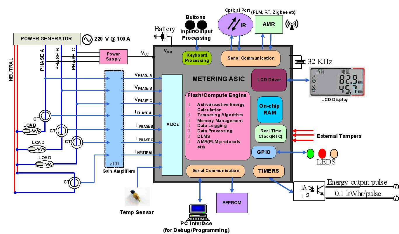
Consumers have been found manipulating their electric meters, causing them to stop, under-register, or even bypass the meter, effectively using power without paying for it. An energy meter is a device that measures the amount of electrical energy supplied...
This design note presents a simple yet feature-rich 16-watt output, universal AC input adapter power supply for modems, hubs, or similar applications. The circuit utilizes a discontinuous mode (DCM) flyback converter topology designed around ON Semiconductor's NCP1027 monolithic current...
This circuit is a radio frequency (RF) field strength meter, similar to a previous model but designed to operate with a lower supply voltage using a single 1.5V battery. The schematic diagram of this RF strength meter circuit is...
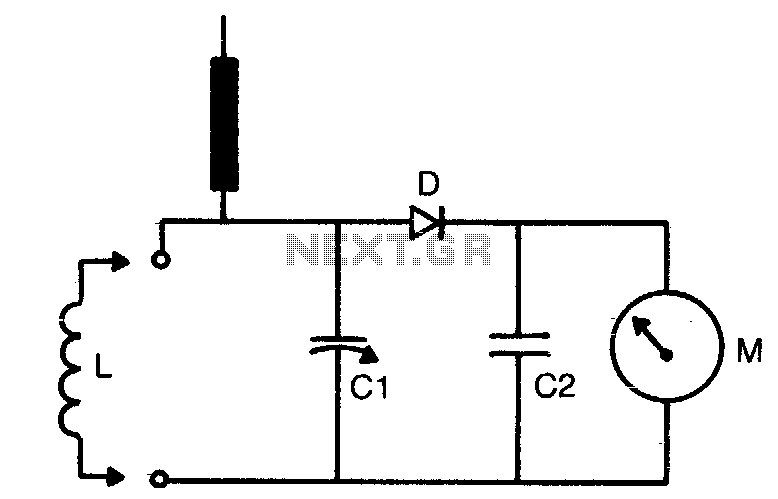
The tuning range is determined by the dimensions of the coil (L) and the setting of the capacitor (C1). Coils can be either plugged in for multi-range use or soldered in place if only a limited frequency range is...
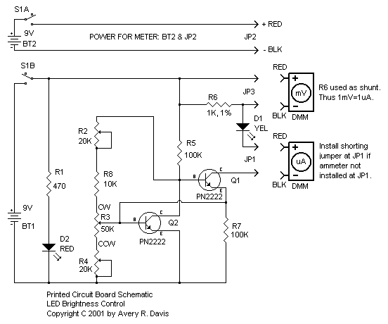
My circuit adds a transistor, to add feedback, and two resistors, to tailor the range of the control, with the result that a single-turn potentiometer gives a control range of about 2 to 30 microamps. I installed my circuit...
Many beginners trying out their skill with QRP TX for the first time have to overcome many problems before they are able to come on the air. One usual complaint is that everything is working fine, but the signal...