
A 75 W Tv Power Supply Operating In Quasi-square Wave Resonant Mode Using Ncp1207 Controller

The digital compass application described employs the Zilog Z8 Encore!® microcontroller, which serves as the core processing unit. The Z8 Encore!® is characterized by its low power consumption and efficient processing capabilities, making it suitable for portable applications. The external compass sensor, likely based on MEMS technology, provides accurate directional data, which is essential for navigation applications.
The communication between the digital compass and the external host is facilitated through two primary interfaces: I2C and UART. The I2C bus is a multi-master, multi-slave, packet-switched, single-ended, serial communication bus that enables multiple devices to communicate with the microcontroller. This bus is particularly advantageous for connecting multiple sensors or peripherals in a compact system. The UART, on the other hand, is a simpler, point-to-point communication protocol that allows for straightforward serial data transmission.
The application note specifies that upon receiving specific commands from the host, the digital compass can toggle outputs to signal interrupts, thereby allowing the host to react to changes in direction. This feature is critical for applications that require real-time responsiveness, such as robotics or mobile devices.
The provided schematics illustrate the connections between the Z8 Encore!® MCU, the external compass sensor, and the communication interfaces. The software implementation is designed to handle commands efficiently and manage data transmission over both I2C and UART. The APIs facilitate interaction with the digital compass, allowing developers to integrate the compass functionality into their applications seamlessly.
In summary, this application note serves as a comprehensive guide for developers looking to implement an 8-direction digital compass using the Zilog Z8 Encore!® MCU, providing both the hardware schematics and the necessary software tools to achieve effective communication and operation.This Application Note demonstrates a simple 8-direction digital compass application using Zilog`s Z8 Encore! ® MCU and an external sensor- compass hardware. Communication ports are pro- vided for the digital compass to receive commands and send status on the I 2 C bus as well as the UART from/to an external host.
According to the command received , the digital compass toggles an output that generates an interrupt for a specific direction. This Application Note provides the schematics and software to implement the Digital Compass appli- cation. It also provides host-side Application Pro- gramming Interface (APIs) to communicate with the Z8 Encore!
MCU-based digital compass. The host CAN be any processor with UART and/or I 2 C peripherals. However, the APIs are written based on using Z8 Encore! MCU as an external host. 🔗 External reference
Related Circuits

The main power supply to the system must be a regulated 12 volts DC with a minimum input from the train control AC or DC power supply of 13.5 VAC connected to pos 3 and 4 of the rectifier...
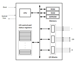
Microcontrollers are integrated circuits that consist of a microprocessor along with additional units such as memory and input/output peripherals. This implementation allows for savings in time, space, and cost. Microcontrollers are commonly abbreviated as MCU (Microcontroller Unit), µC, or...
The figure illustrates the automatic watering control circuit for bean sprouts. The controller includes a step-down rectifier circuit, a power outage detection component (IC3), a timing control circuit (IC1), and a temperature control circuit (IC2). The step-down rectifier circuit...
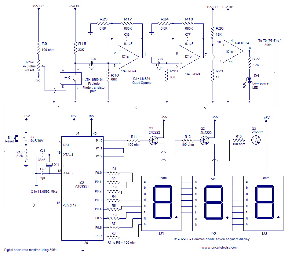
A basic full wave rectified power supply is shown below. The transformer is chosen according to the desired load. For example, if the load requires 12V at 1amp current, then a 12V, 1 amp rated transformer would do. However,...
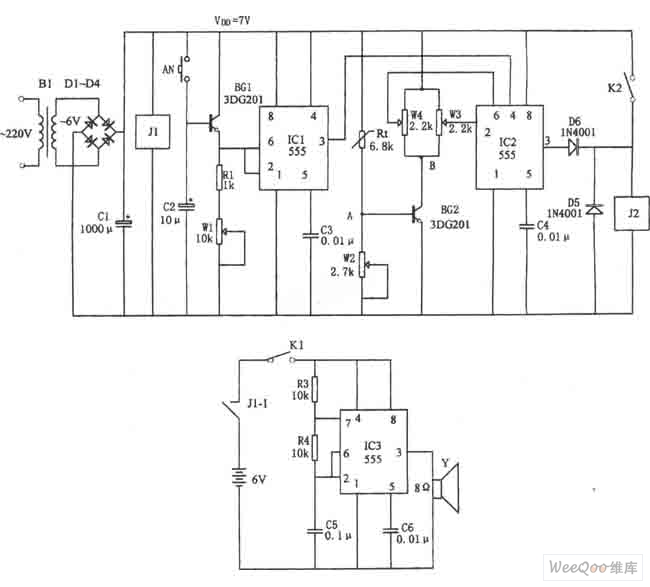
Heart rate monitor using an 8051 microcontroller. It measures the heart rate from the fingertip using an IR diode and phototransistor pair (Photoplethysmography). The AT89S51 microcontroller is utilized in this application. The heart rate monitor circuit operates based on the...
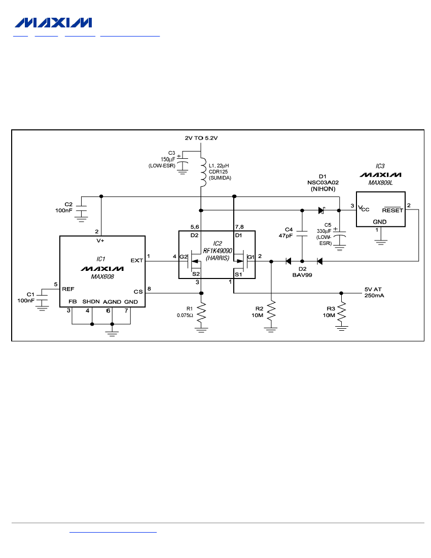
To ensure a full-load start-up, the additional circuitry in this regulated boost converter disconnects the load until the output voltage reaches regulation. Proper operation necessitates a gate-drive voltage adequate to maintain low on-resistance in the switching MOSFET; however, during...
Warning: include(partials/cookie-banner.php): Failed to open stream: Permission denied in /var/www/html/nextgr/view-circuit.php on line 713
Warning: include(): Failed opening 'partials/cookie-banner.php' for inclusion (include_path='.:/usr/share/php') in /var/www/html/nextgr/view-circuit.php on line 713