
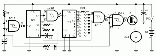
Model Train Diesel and Horn Circuit
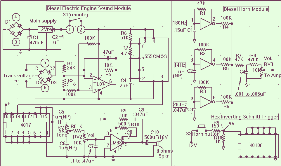
The circuit described involves a power supply system for a train control module, emphasizing the need for a regulated 12V DC output. The input to the power supply is derived from an AC or DC source, specifically requiring a minimum of 13.5 VAC. This input voltage is connected to positions 3 and 4 of a rectifier bridge, which converts the AC voltage to DC. The rectifier bridge is crucial for ensuring that the output remains stable and positive, regardless of the train's direction.
The ground bus for the 12V regulated supply must be connected to the system ground, establishing a common reference point for the entire circuit. This connection is vital for minimizing noise and ensuring reliable operation of the electronic components involved.
Additionally, the circuit features an independent speed reference voltage that can be sourced directly from the train speed control module. Alternatively, it can be derived from the tracks by connecting to positions 5 and 6 of the rectifier bridge. This flexibility allows for accurate speed control and monitoring, as the output from the rectifier bridge consistently provides a positive voltage signal corresponding to the train's speed, regardless of its direction.
For signal processing, a FET input operational amplifier (TL071) is utilized. This choice is made to minimize offset voltage, which is crucial for precision applications. The TL071 has a significantly lower average offset voltage of 1.15V compared to the standard 741 op-amp, which has an offset voltage of 2.3V. By using the TL071, the circuit can maintain better accuracy without the need for additional offset correction circuitry, which simplifies the design and enhances performance.
Overall, this schematic outlines a robust and efficient power supply and control system for train operations, ensuring reliable voltage regulation and precise speed control through thoughtful component selection and circuit design.The main power supply to the system must be a regulated 12 volts DC with a minimum input from the train control AC or DC power supply of 13.5 VAC connected to pos 3 and 4 of the rectifier bridge . The ground bus of the regulated 12 volts supply must be connected to the system ground , The independent speed reference voltage is taken directly from the train speed control module or can be taken by connecting directly from the tracks to positions 5 and 6 of the rectifier bridge .The output of this bridge will always be a positive speed voltage signal whichever direction the train is going.
The op-amp used is a FET input type ( TL071) for minimum offset voltage without having to use a zero offset voltage circuit . The offset voltage for the 741 was found to be much too high at 2.3v while the TL071 average offset of 1.15 volts was ideal to ma
🔗 External reference
Related Circuits
Two circuits for laser transmitters are described. The first circuit utilizes a simple laser pointer module, with 3 or 5mW devices functioning effectively. Higher power units are often imported from the USA or Hong Kong compared to UK approved...
How to create a Joule Thief circuit to power a clock, including circuit details and tips for construction. The Joule Thief circuit is a simple and efficient boost converter that allows the extraction of usable voltage from low-voltage sources, such...
The TDA7088 features a frequency-locked-loop (FLL) system with an Intermediate Frequency (IF) of approximately 70 kHz. This circuit can be powered using a 3-volt battery cell or a regulated power supply. The TDA7088 is a highly integrated FM radio receiver...
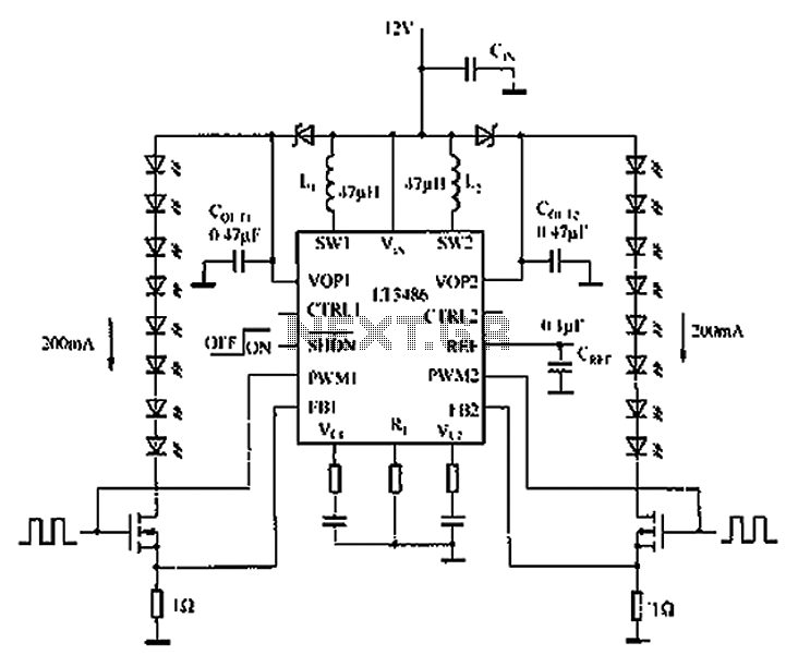
The automotive LED driver circuit diagram utilizes the LT3486. The LED is employed in the car's central high-mounted stop lamp (CHMSL), providing advantages such as faster achievement of the set brightness, higher efficiency, longer lifespan, and simplified design and...
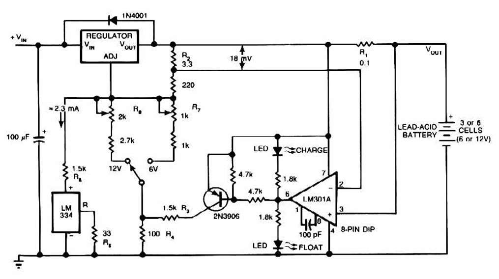
The schematic for this charger is straightforward. It is designed to charge a Gel Cell or other lead-acid types. This simple battery level monitor circuit can indicate the charging process in a 12 Volt lead-acid battery or tubular battery....
3V battery-powered circuit that emits a beep after a fixed delay of several minutes. This circuit was created in response to requests from users seeking a timer functionality. The described circuit operates on a 3V power supply, making it suitable...