
A Bedside Lamp Timer Circuit Schematic With CD4060 IC

The Bedside Lamp Timer Circuit is designed to provide a timed illumination feature using the CD4060 IC, which serves as a timer and oscillator. The circuit operates on a voltage range typically between 3V to 15V, making it versatile for various power supply options.
The CD4060 IC is configured in such a way that it generates a square wave output, which can be used to control the operation of the lamp. The timing period is determined by external resistors and capacitors connected to the IC. For a 30-minute operation, specific resistor and capacitor values must be selected to achieve the desired timing.
The blinking LED acts as a visual indicator of the remaining time, flashing at a rate that becomes more frequent as the timer approaches its end. This is typically accomplished by connecting the LED to a separate output pin on the CD4060 that is configured to toggle at a specific frequency during the last 6 minutes of operation.
Additionally, the circuit may incorporate a relay or a transistor switch to control the lamp's power, ensuring safe operation and isolation from the low-voltage control circuit. A diode may also be included in the circuit to protect against back EMF generated by the relay coil.
Overall, the Bedside Lamp Timer Circuit with CD4060 provides a practical solution for timed lighting, enhancing convenience in various applications such as bedside lamps, night lights, or other timed illumination needs.The following circuit shows the Bedside Lamp Timer Circuit With CD4060 IC. 30 minutes operation, Blinking LED signals 6 last minutes before .. 🔗 External reference
Related Circuits
A single hand clap will be picked up by the electric mic which is coupled through C1 into the op amp IC1. The output of IC1 triggers the 555 IC timer IC2 which is configured as a monostable multivibrator....
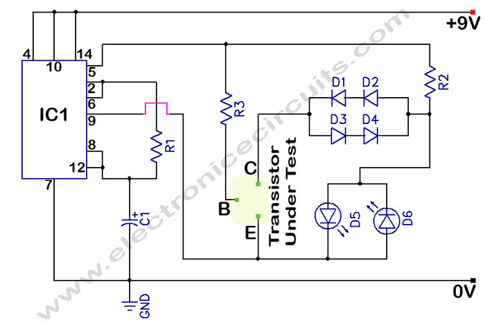
The circuit is a transistor tester schematic that indicates the condition of a transistor using two LEDs. It is designed to test a good NPN transistor. The transistor tester circuit operates by utilizing two light-emitting diodes (LEDs) to provide a...

The TEA5551T monolithic integrated radio circuit can be utilized to design an AM radio receiver, intended for use as a portable radio receiver with headphones. The TEA5551T radio receiver circuit encompasses all necessary components for a complete AM receiver,...

The circuit utilizes the SH803 flash IC, which can store eight different programs and offers various dimming options and light speed adjustments. A button is provided to trigger the control terminal SB on the 9-pin connector for program selection,...
The schematic shown below is a 555 timer circuit. The NE555 is a well-known integrated circuit that comes in an 8-pin dual in-line package (DIP). There is a vast array of circuits utilizing the 555 IC, which contributes to...
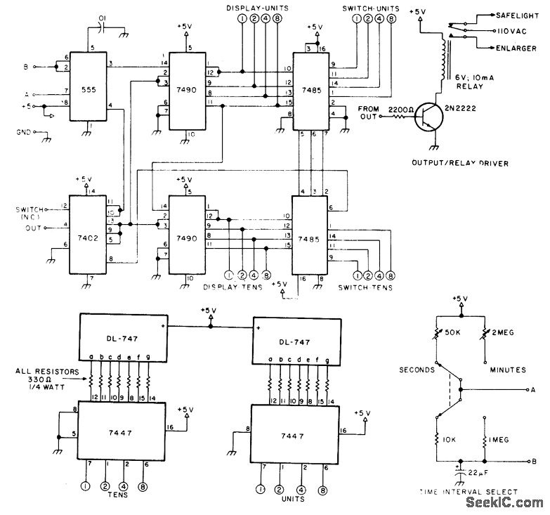
The circuit provides timing capabilities ranging from 1 second to 99 seconds and from 1 minute to 99 minutes, featuring a 2-digit LED indicator that displays the elapsed time. The desired timing interval is set using BCD thumbwheel switches....