
In-Circuit Transistor Tester
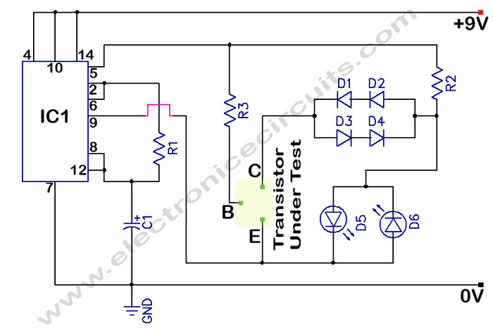
The transistor tester circuit operates by utilizing two light-emitting diodes (LEDs) to provide a visual indication of the transistor's functionality. The circuit typically incorporates a power supply, resistors, and a few other passive components to ensure proper operation.
When an NPN transistor is inserted into the designated socket of the circuit, the tester applies a small current through the base of the transistor. If the transistor is functioning correctly, it will allow a larger current to flow from the collector to the emitter, illuminating one of the LEDs, which indicates that the transistor is in good condition.
In contrast, if the transistor is faulty or damaged, the circuit will not allow the current to flow effectively, resulting in the other LED lighting up or no LEDs lighting at all. This simple yet effective design enables users to quickly determine the operational status of NPN transistors without the need for complex testing equipment.
The circuit can be enhanced with additional features such as a switch to select between testing NPN and PNP transistors, or the inclusion of a digital display for more precise readings. Furthermore, incorporating a variable resistor can allow adjustments to the current applied to the base, accommodating different transistor specifications. Overall, this transistor tester circuit provides an efficient and straightforward method for evaluating the health of transistors in various electronic applications.In Circuit Transistor Tester Schematic Here is a circuit that can indicate the condition of a transistor by using two LEDs. A good NPN transistor. 🔗 External reference
Related Circuits
The final article on bipolar junction transistors (BJT) presents a variety of circuits, some practical and others more experimental. These circuits are capable of amplifying signals, filtering high and low frequencies, generating white noise, and flashing lamps. They can...
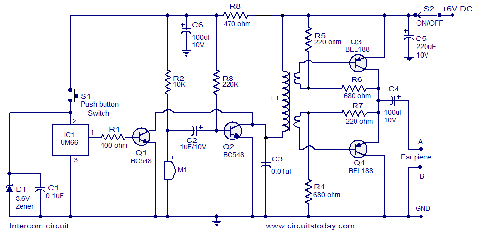
A straightforward intercom circuit designed using transistors. It does not require a changeover switch and can be used similarly to a telephone. This intercom circuit utilizes transistors to facilitate communication between two or more stations without the need for complex...
The output can also be taken from the collector terminals of the transistors, as illustrated in the circuit below. To understand the operation of the circuit, it is recommended to read about how a transistor functions as a switch. In...
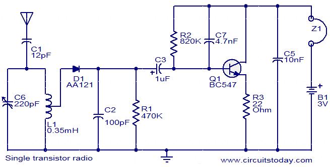
The circuit diagram of a simple radio that uses one transistor and a few other passive components. Component: Diode, Capacitor, Inductor, Resistor. The circuit design for a simple radio receiver typically incorporates a single transistor as the active amplification element,...

None of those devices is very suitable. The drivers aren't specified to operate with 3.3V gate signals, and although the typical graph shows that a... The devices referenced in the original input are not appropriate for the intended application due...

This circuit allows for testing quartz resonators within a frequency range of 32 kHz to 24 MHz. The operational status of the quartz resonator is indicated through a diode that signals an LED and emits an acoustic signal. A...
Warning: include(partials/cookie-banner.php): Failed to open stream: Permission denied in /var/www/html/nextgr/view-circuit.php on line 713
Warning: include(): Failed opening 'partials/cookie-banner.php' for inclusion (include_path='.:/usr/share/php') in /var/www/html/nextgr/view-circuit.php on line 713