
A circuit diagram of a high-speed switch constituted triggered rising MIC5158
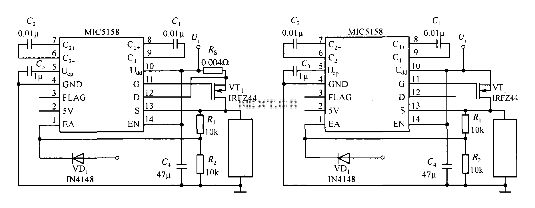
The MIC5158 is a precision voltage reference and high-speed switching device that is commonly utilized in various electronic applications requiring rapid signal transitions. In a typical high-speed switching circuit, the MIC5158 is integrated to ensure clean and fast rising edges, which are critical for maintaining signal integrity in high-frequency environments.
The circuit diagram featuring the MIC5158 typically includes several key components: the MIC5158 itself, resistors for setting the reference voltage, capacitors for filtering and stability, and possibly additional transistors or MOSFETs to drive larger loads. The rising edge of the signal generated by the MIC5158 is characterized by a swift transition from a low to a high state, which is essential for applications such as digital logic circuits, RF transmission, and high-speed data communication.
In the schematic, the input signal is fed into the MIC5158, which processes the signal to produce the desired output with a steep rising edge. The timing characteristics of the output can be adjusted by selecting appropriate external components, such as capacitors and resistors, which influence the charge and discharge rates of the internal circuitry.
Overall, the integration of the MIC5158 in high-speed switching applications enhances performance by reducing propagation delays and improving the overall responsiveness of the circuit, making it an invaluable component in modern electronic designs.MIC5158 constitute the rising edge of the high-speed switching circuit diagram.
Related Circuits
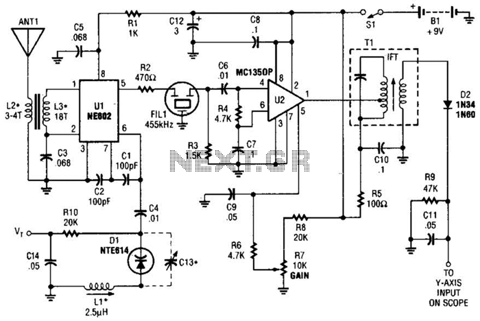
This circuit is designed for monitoring an amateur band or a specific segment of the radio spectrum. It utilizes an NE602 mixer-oscillator chip to generate a 455-kHz intermediate frequency (IF) signal. This signal is amplified by U2 and subsequently...
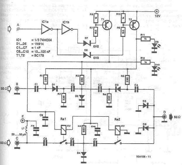
This antenna selector circuit diagram electronic project is constructed using standard electronic components and facilitates the switching between two FM antennas through a logic signal. The gates IC1b and IC1a manage the switching and interface between the required logic...
The amplifier circuit utilizing the STK4050 integrated circuit (IC) is known for its robustness and high quality. This article presents a 200-watt power amplifier circuit based on the STK4050. The circuit features an advanced auto wiring diagram with color-coded...
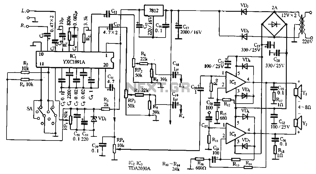
The ptPC1891A application circuit features a working state switch (SA) with a total of four options. It primarily utilizes ICs 11 and 12 to set different logical levels, as referenced in Table 5-12. The high level is denoted as...
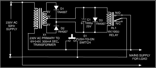
This is a low-cost protection circuit designed to safeguard electrically operated home appliances, such as TVs, DVD players, refrigerators, and other devices, during sudden power outages and the subsequent restoration of mains supply. Appliances like refrigerators and air conditioners...
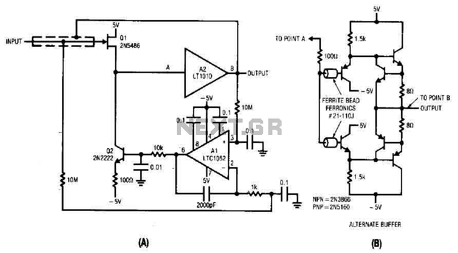
The difference between the amplified signals is utilized to establish the bias for Q1 and Q2 current channels. Q1 regulates the gate-source voltage (VGS) to the necessary level corresponding to the circuit's input and potential output. A 2000 pF...