
Schematic Circuit Ic Stk
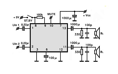
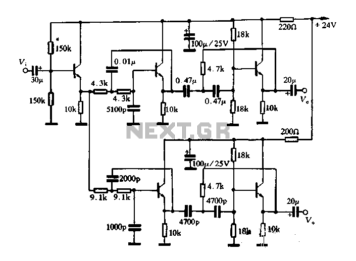
The STK4050V is a high-power audio amplifier IC designed to deliver up to 200 watts of audio power in a single-channel configuration. The circuit schematic includes essential components and connections necessary for optimal performance, ensuring high-quality audio output while managing thermal and electrical characteristics effectively.
The amplifier circuit's design emphasizes stability and efficiency, incorporating feedback mechanisms to minimize distortion and enhance sound clarity. The use of advanced electronic components allows for improved frequency response and dynamic range, making it suitable for various audio applications. The wiring diagram aids in proper assembly and troubleshooting, ensuring that users can effectively implement the circuit in their projects.
In summary, the STK4050-based amplifier circuit is a reliable solution for high-quality audio amplification, characterized by its robust design and capability to deliver substantial power with manageable distortion levels. The accompanying diagrams and symbols facilitate easy understanding and implementation of the circuit, making it accessible for both novice and experienced electronics enthusiasts.Amplifier circuit with IC STK is tough and good quality. In this article an amplifier circuit with IC STK another base. Power "Amplifier 200Watt By STK4050. Auto Wiring Diagram Advanced Symbols. Wiring Diagrams Color Coding For The Speaker Wiring On A 1986 2005. Circuits 2004 2007. Wiring Diagrams If You Plan. Because this amplifier circuit oper ates in "pure" Class-B (something of a contradiction of terms, I think), the high frequency distortion will be relatively high, and. Electronic circuit diagram, Circuitdiagram. net provides electronic circuit diagram and design schematic diagram such as alarm circuit, power supply, inverter circuit, audio circuit, .
Circuit diagram, This tremolo effect circuit uses the xr2206 and the tca730 ic which is designed as an electronic balance and volume regulator with frequency correction. [amp-circuits] stk 4050 - 200watt power amplifier circuit, Amplifier circuit with ic stk is tough and good quality.
in this article an amplifier circuit with ic stk another base. power "amplifier 200watt by stk4050. Circuit diagram: auto electrical symbols, Auto wiring diagram advanced symbols. wiring diagrams color coding for the speaker wiring on a 1986 2005. circuits 2004 2007. wiring diagrams if you plan. Amplifier circuit schematic diagram | skema rangkaian, Because this amplifier circuit operates in "pure" class-b (something of a contradiction of terms, i think), the high frequency distortion will be relatively high, and. High voltage inverter circuit diagram | gambar skema, This inverter circuit works with a transistor and transformer and other components to increase the voltage becomes high.
input supply voltage ranging from. Audio ic - circuits - electronic circuits, tv schematics, Audio integrated circuits (ic) cross reference search (manufacturer pn): results 1606 1606 references in database max list size 1 for transistor and diode please. Stk4050v 200 watt audio amplifier circuit diagram, This 200 watt audio amplifier circuit diagram is based on stk4050v high power audio amplifier ic and is designed do deliver up to 200 watts audio power on a single.
100w rms amplifier|audio|free circuit diagram and, Here the 100w rms amplifier schematic diagram: this circuit is quite simple but will give you high quality audio output. read detail explanation here download large. 🔗 External reference
Related Circuits
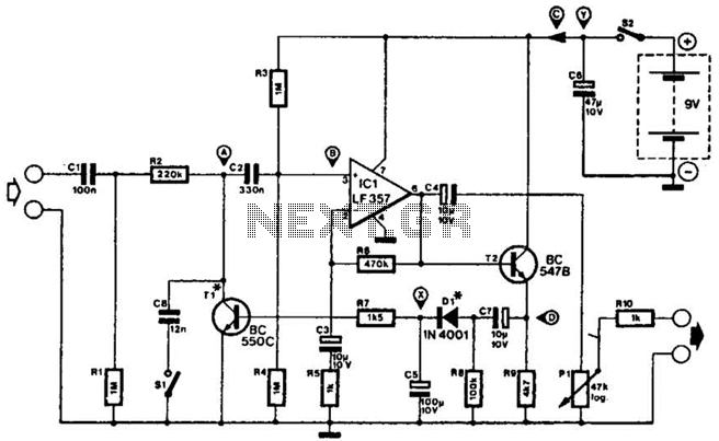
This compressor will compress a 25-mV peak-to-peak (p-p) audio signal to a 20-V p-p output, maintaining input levels between 1.5 V p-p and 3.5 V p-p, with a frequency response ranging from 7 Hz to 67 kHz. It is...
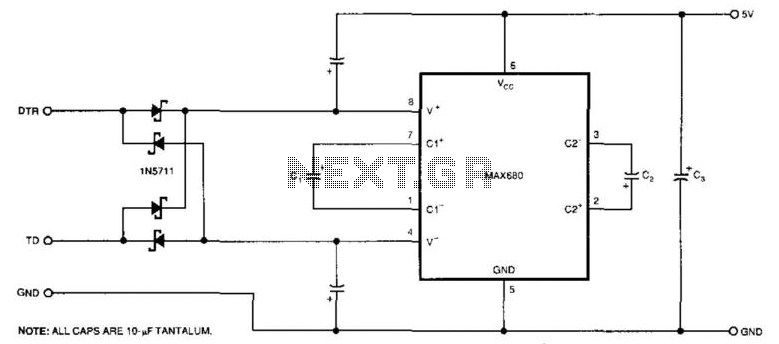
The circuit demonstrates a method for powering CMOS integrated circuits (ICs) using RS-232C lines. The MAX680 is typically employed to generate a voltage equal to ±2 Vcc. This circuit operates in the opposite manner, accepting ±10.5 to ±12V from...
The circuit operates as a light-to-sound conversion system, featuring a light electric sound conversion circuit with two simple fiber optic connectors for experimental purposes. The electrical diagram illustrates the conversion circuit, where audio signals from a radio, music player,...
This article describes a band-pass filter circuit diagram utilizing transistors. A band-pass filter is an essential electronic circuit that allows signals within a certain frequency range to pass while attenuating frequencies outside that range. The circuit typically consists of a...
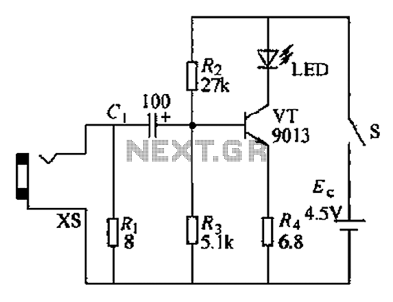
In certain applications, the current from a non-rectified voltage power supply circuit is insufficient. A light-emitting diode (LED) rectifier circuit can be employed to address this issue, serving as a power indicator. It is important to ensure that the...
This circuit consists of five transistor time relay circuits designed for time relay exchange. It utilizes two different power supplies, maintaining the same circuit configuration. The delay time can be adjusted by modifying a potentiometer. The parameters for the...
Warning: include(partials/cookie-banner.php): Failed to open stream: Permission denied in /var/www/html/nextgr/view-circuit.php on line 713
Warning: include(): Failed opening 'partials/cookie-banner.php' for inclusion (include_path='.:/usr/share/php') in /var/www/html/nextgr/view-circuit.php on line 713