
Simple Spectrum Analyzer Adaptor For Scopes Circuit
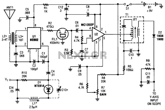
The circuit operates by leveraging the NE602 chip, which functions as both a mixer and an oscillator. The chip receives an RF signal from the amateur band and mixes it with a local oscillator signal to produce the 455-kHz IF signal. This intermediate frequency is crucial for further processing, as it is easier to amplify and analyze compared to the original RF signal. The amplifier U2 enhances the strength of the IF signal, ensuring that it is adequate for detection.
Detector D2 plays a pivotal role in demodulating the IF signal, converting it into an audio or baseband signal that can be visualized on the oscilloscope. The Y-axis of the oscilloscope displays the amplitude of the detected signal, allowing for real-time monitoring of the frequency spectrum. The horizontal axis, driven by VT, enables the user to sweep across the frequency range, providing a comprehensive view of the signals present within the selected amateur band.
Coils L2 and L3 are critical components in this circuit, as they are specifically designed to resonate at the desired frequencies within the 10 to 15 MHz range. The choice of using toroidal cores from Amidon Associates ensures minimal electromagnetic interference and optimal performance. The variable inductor LI allows for fine-tuning of the circuit, enabling adjustments to be made for different operating conditions or specific frequencies of interest.
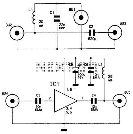
Overall, this circuit serves as an effective tool for amateur radio enthusiasts and spectrum monitoring applications, providing a straightforward means to visualize and analyze signals within a designated frequency range. Suitable for monitoring an amateur band or a segment of the radio spectrum, this simple adaptor uses an NE602 mixer-oscillator chip to produce a 455-kHz IF signal, which U2 amplifies, then feeds to detector D2 and the Y axis of an oscilloscope. VT is used to drive the horizontal axis input of a scope. L2 and L3 are coils suitable for the frequency range in use. For this circuit, coils are shown for the 10- to 15-MHz range. L2 and L3 are wound on Amidon Associates, T-37 or T-50 toroidal cores, and LI is a commercial or homemade variable inductor, etc. 🔗 External reference
Related Circuits
VOX is a voice-controlled switch commonly used for microphones, serving as a replacement for the traditional switching button. The actuating threshold is adjusted through the volume potentiometer. The VOX (Voice Operated Switch) circuit functions by detecting sound levels and activating...
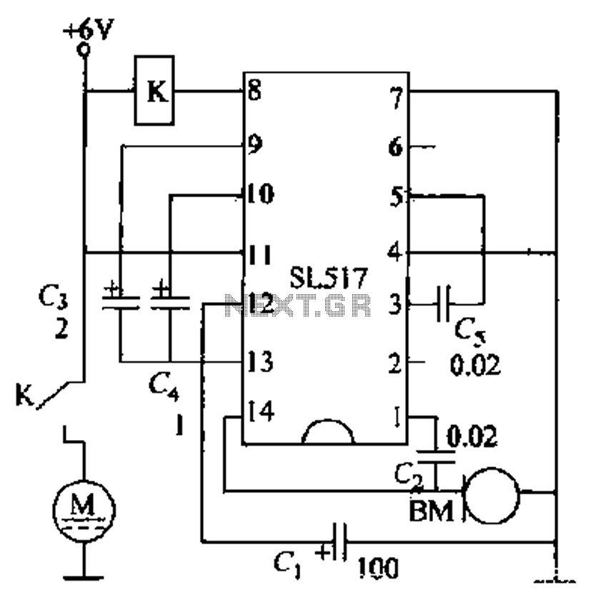
Electric cars utilize a voice circuit principle, where sound signals are captured by a microphone (BM) and processed. The signal is then coupled through a capacitor to an integrated circuit (IC), which includes an internal amplifier that boosts the...
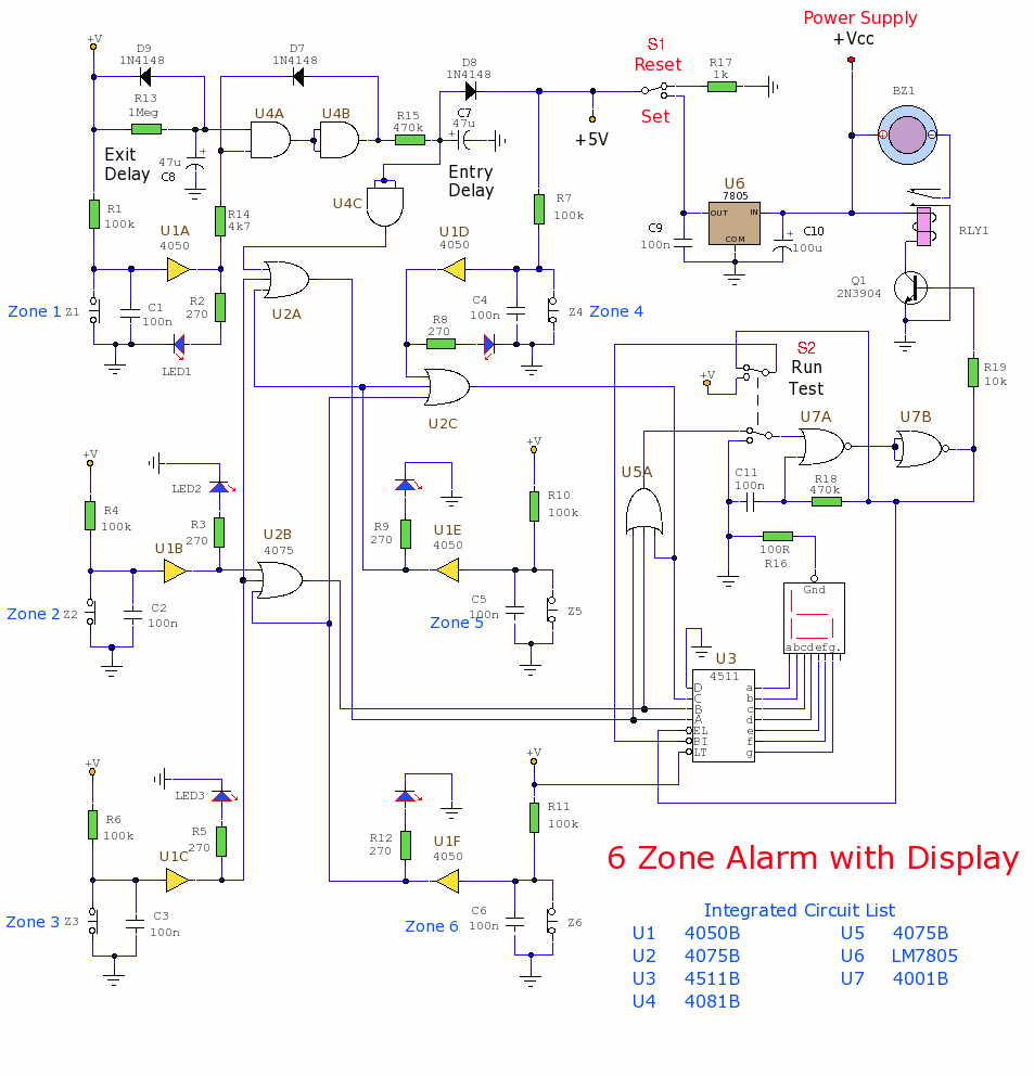
This section includes intruder alarms for homes, cars, and motorcycles, as well as power failure alarms, water level alarms, and a snore detector. All circuits are organized alphabetically on the Circuit Index page and chronologically on the update page....
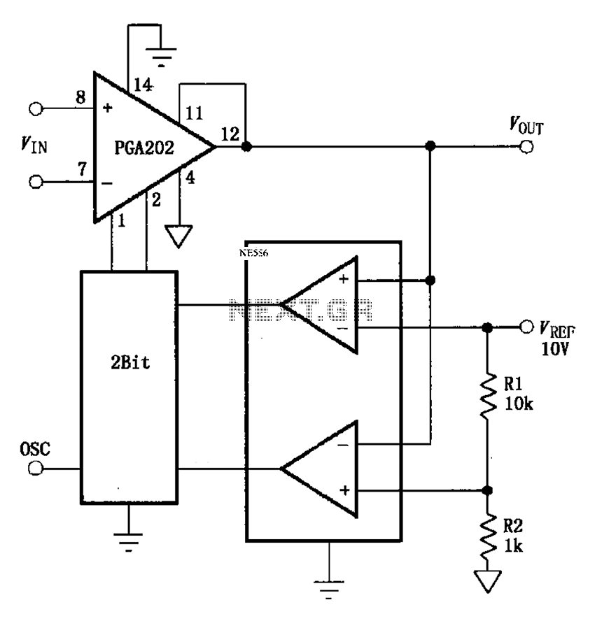
The automatic range switching circuit consists of PGA202, comparators, and counters, as illustrated in the figure. The comparator at the output compares VOUT with VREF. When VOUT exceeds 10V, the comparator generates a low signal, causing the up/down counter...
This wideband antenna preamplifier has a gain of approximately 20 dB from 40 to 860 MHz, covering the entire VHF, FM, commercial, and UHF bands. A phantom power supply delivers DC power to the preamplifier through the coaxial cable...
One of the critical components is a PWM speed controller, allowing for fine speed adjustments instead of just an "on" mode that runs at full power. This is important for safety. A basic stamp microcontroller was purchased, which includes...