
iPod Passive Preamplifier
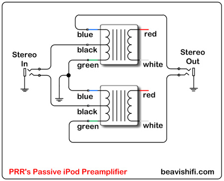
A passive preamplifier is a circuit designed to amplify audio signals without the use of active components such as transistors or operational amplifiers. Instead, it relies on passive components like resistors, capacitors, and transformers to increase the signal level. This type of preamplifier is ideal for portable media players, as it can improve sound quality by providing a better impedance match between the media player and the car's audio system.
The basic design of a passive preamplifier involves connecting the output of the portable media player to the input of the preamplifier. A potentiometer can be included to allow for volume control, adjusting the signal level before it reaches the car's audio system. The output of the preamplifier is then connected to the car's auxiliary input or directly to the amplifier.
Key components in the circuit may include:
1. **Resistors**: Used to create voltage dividers for signal attenuation and to set input/output impedance levels.
2. **Capacitors**: Employed for coupling and decoupling signals, blocking DC while allowing AC audio signals to pass through.
3. **Potentiometer**: Serves as a variable resistor to adjust the audio signal level, providing user control over volume.
4. **Connectors**: RCA or 3.5mm jacks may be used for interfacing with the media player and the car audio system.
The circuit layout should ensure minimal signal loss and noise interference. Proper grounding and shielding techniques should be implemented to maintain audio fidelity. The passive nature of the preamplifier makes it a cost-effective solution for enhancing audio output without the need for an external power source, making it suitable for mobile applications.Build a simple passive preamplifier for your iPod, Zune or other portable media player. Great for the car. 🔗 External reference
Related Circuits
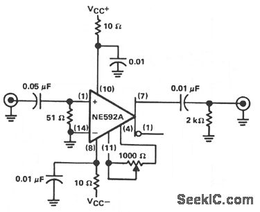
The circuit provides a voltage gain of 20 ±0.1 dB within a frequency range of 500 kHz to 50 MHz. The low-frequency response of the amplifier can be enhanced by increasing the value of the 0.05 µF capacitor connected...
This circuit was submitted by Graham Maynard from Newtownabbey, Northern Ireland. It has an exceptionally fast high-frequency response, as demonstrated by applying a 100kHz square wave to the input. All graphs were produced using Tina Pro. The circuit in question...
The circuit is based on a single operational amplifier integrated circuit designed to produce a modular preamplifier that operates in Class A configuration. The modular preamplifier circuit utilizes a single operational amplifier (op-amp) integrated circuit, which serves as the primary...
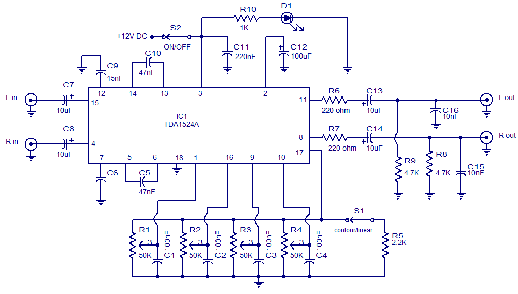
The circuit diagram presents a high-quality stereo preamplifier featuring tone control, utilizing the TDA1524 IC from Philips. This integrated circuit requires minimal external components, operates with low noise, and accommodates a broad power supply voltage range. Potentiometers R1 through...
The Software Defined Radio (SDR) hardware, in its most basic configuration, includes a wideband switched balanced mixer and a low noise LF amplifier. This straightforward hardware demonstrates remarkable sensitivity and linearity, making it suitable for both testing and regular...
This document serves as a supplementary guide to numerous existing resources that detail the construction of a USB charger. It is assumed that the reader possesses a basic understanding of electronics. The construction of a USB charger typically involves a...
Warning: include(partials/cookie-banner.php): Failed to open stream: Permission denied in /var/www/html/nextgr/view-circuit.php on line 713
Warning: include(): Failed opening 'partials/cookie-banner.php' for inclusion (include_path='.:/usr/share/php') in /var/www/html/nextgr/view-circuit.php on line 713