
6W Morse-Code Transmitter 7Mhz Circuit

The CW transmitter circuit utilizes vacuum tubes, which are known for their ability to amplify signals and operate at high voltages. The design employs a wooden base to support the breadboard layout, allowing for easy modifications and adjustments. The use of components salvaged from old table radios not only promotes recycling but also provides cost-effective solutions for building the circuit.
In the circuit, V3 serves as a ballast resistor, which is crucial for stabilizing the current and ensuring consistent operation of the vacuum tube. The choice of a 75- or 100-ohm, 5-watt resistor allows for flexibility in sourcing components while maintaining the desired electrical characteristics.
Inductors L1 and L2 play a significant role in the circuit's operation. L1, with its 15 turns of hookup wire, is designed to provide the necessary inductance for the circuit's frequency requirements. The 2-inch form used for winding L1 ensures that the inductor maintains a compact size while achieving the desired electrical performance. L2, with 7 turns wound over L1, acts as a coupling inductor, enhancing the circuit's efficiency by transferring energy between stages effectively.
Safety precautions are paramount, particularly due to the presence of high voltages (up to 160 V) on components Y1 and V2. Proper insulation and careful handling are essential to prevent electrical shock and ensure safe operation of the transmitter. Overall, this CW transmitter circuit exemplifies the enduring utility of vacuum tubes in modern electronics, showcasing their application in RF transmission while emphasizing the importance of safety and component sourcing. The vacuum tube is still alive and useful in some applications, as in this CW transmitter, The circuit was built in old-fashioned breadboard style on a wooden base. Old table radios are a good source of parts for this circuit. V3 is used as a ballast resistora 75- or 100- 5-W resistor could be substituted. LI is 15 turns of hookup wire on a form 2 long. L2 is 7 turns of the same wire. L2 is wound over LI. Be careful as up to 160 V is present onYl and V2.
Related Circuits
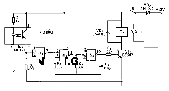
An anti-theft car audio system circuit is depicted, powered by a 12V DC supply from the car battery. Upon closing switch S1, the light-emitting diode in optocoupler IC1 activates, causing the phototransistor to conduct. This results in a high-level...
This is an aerial current power supply with a continuously adjustable stabilized output ranging from 0 to 30VDC. The circuit also incorporates an electronic current limiter that effectively controls the output current from a few milliamperes (2 mA) to...
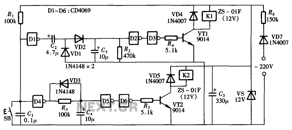
A one-button control switch is designed to control two relays, each of which can switch the load power on and off as needed. The circuit primarily consists of a hex inverter CD4049 and two self-locking DC relays. The circuit utilizes...
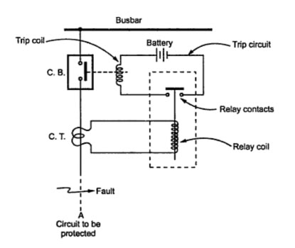
A trip unit is electrically connected in parallel with a current-limiting polymer element in series with circuit breaker contacts to function as a shunt resistance for the polymer element. It becomes energized when the polymer element transitions to its...
The main circuit of the 6-channel mixer consists of six input channels. Channels 1-4 are mono, while channels 5-6 are designed for music use. The number of input channels can be increased as desired. The output of each channel...
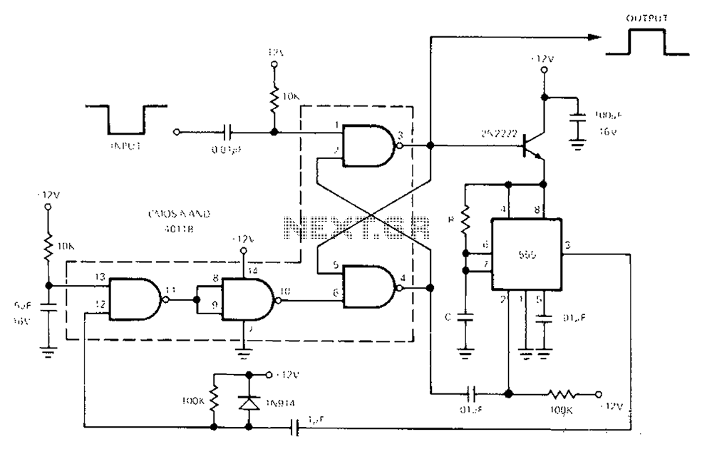
The 555 Timer facilitates a low-loss single-shot circuit and interfaces with the CMOS4011B NAND gate circuit. The standby power consumption is less than 50 µA. When the one-shot circuit is activated, the current consumption is 4.5 mA, and the...