
Synchronous motor thyristor excitation circuit

The excitation device is critical for the operation of synchronous motors, which require precise control of rotor excitation to maintain synchronism with the stator's rotating magnetic field. The use of three identical RC phase-shift flip-flops in the triggering circuit provides a robust method for generating the necessary phase shifts. Each flip-flop can be configured to introduce a specific delay, effectively creating a phase shift that can be finely tuned using the adjustment potentiometers.
The adjustment potentiometers RP3 to RPs play a vital role in calibrating the phase shift within the circuit. By varying the resistance in the RC network, the phase angle can be set between 0 and 150 degrees. This flexibility allows for precise control of the excitation current supplied to the rotor, which is essential for optimizing the performance of the synchronous motor under varying load conditions.
The design of the excitation circuit must ensure stability and reliability. The RC phase-shift network must be designed to minimize noise and interference, which can adversely affect the operation of the synchronous motor. Additionally, the choice of components for the flip-flops and the potentiometers should be made with consideration for their thermal characteristics and voltage ratings to ensure long-term operation without failure.
Overall, the described excitation device is a sophisticated control system that allows for enhanced performance and efficiency of light-duty synchronous motors, making it suitable for various industrial applications where precise motor control is required.The excitation device for light duty synchronous motor 625kW initiated. Triggering the device circuit consists of three identical RC phase-shift flip-flops. Adjustment potentiometer RP3 ~ RPs, make RC phase shift bridge phase O. ~ 150. Changes to control the size of the rotor excitation current.
Related Circuits
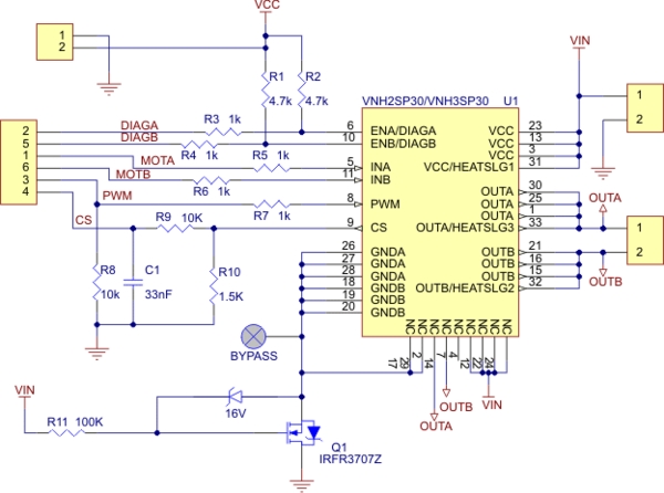
Need more current? If you have a larger motor ready for use, the Pololu High Current Motor Driver Board 14A 6V-16V is the ideal solution. Connect three digital lines to your microcontroller (five if error condition feedback is desired),...
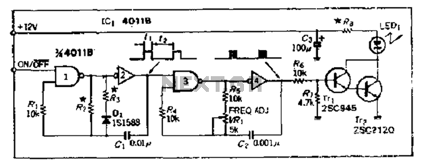
The 4000 Series 4011B is a NAND gate used in conjunction with a 4AI NAND gate circuit group to create two loops of an unstable multivibrator. The first NAND gate and the second NAND gate operate at approximately 1...
The BTS412B functions as two high-side power MOSFET switches, while the BU271L components rated for 50V serve as the low-side switches. Together, these elements can form a bi-directional H-bridge DC motor drive circuit, as depicted in Figure 11-1l. This...
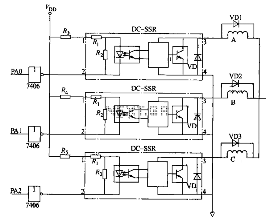
The figure illustrates that the DC Solid State Relay (SSR) in the input stage functions as an opto-isolator. When the switch output is high, the driver circuit inverts this signal to low. This process involves a light-emitting diode (LED)...

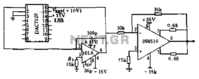
The circuit has four inputs. The voltage gain between each input and the output is maintained at unity by the relative values of the 470 kΩ input resistor and the 470 kΩ feedback resistor. The described circuit operates as a...
The automatic toilet flusher is designed to restructure the traditional flushing mechanism, allowing for a single, reliable flush after each use. It features energy-saving capabilities and a long-lasting chip, ensuring ease of use even when disconnected from the power...