
A CMOS the spot welding time adjustment circuit b

The described circuit employs complementary metal-oxide-semiconductor (CMOS) technology to facilitate precise control over the timing of spot welding operations. The cycle adjustment feature is crucial for optimizing the welding process, allowing users to select the appropriate duration for different materials and thicknesses. The range of 1 to 99 cycles provides flexibility, although typical usage often requires fewer cycles, with a common setting around 10.
The integration of gates (C036) serves as the logic control elements, enabling the configuration of the desired cycle count. The counters (C180) play a vital role in tracking the number of cycles completed during the welding process, ensuring accurate timing and repeatability. The D flip-flops (C043) are utilized to store the state of the control signals, providing a stable output that can be used to trigger the welding operation.
Additionally, the inclusion of a seven-segment decoder (C036) enhances user interaction by displaying the selected cycle count on an LED display (BS202). This feature allows operators to easily monitor and adjust settings in real-time, contributing to improved operational efficiency and safety.
Overall, the CMOS-based spot welding time adjustment circuit is a sophisticated solution that combines various electronic components to deliver precise control and user-friendly operation, making it suitable for a range of industrial applications.A CMOS constituting the spot welding time adjustment circuit b The number of cycles it uses CMOS device composed of a control circuit, optionally in the range of 1 to 99 cycles to choose from. In actual use, most of them within 10 cycles adjusted enough. Drawing, are integrated with CMOS circuitry; gates 1 to 20 available C036; C180 counter available 21,22; D flip-flops 25, 26 Available C043; seven segment decoder applications C036; LED digital works BS202.
Related Circuits
This circuit is a simple two-transistor (2N2222) mini FM transmitter. No authorization is required for this transmitter according to FCC regulations regarding wireless microphones. When powered by a 9-volt battery and equipped with an antenna no longer than 12...
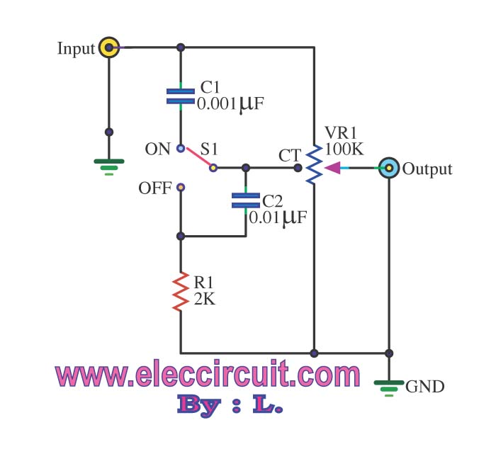
The passive tone control circuit is designed to adjust the bass without expansion, utilizing resistors (R) and capacitors (C). It functions as a frequency filter and is easy to construct, requiring no external power supply. This circuit can be...
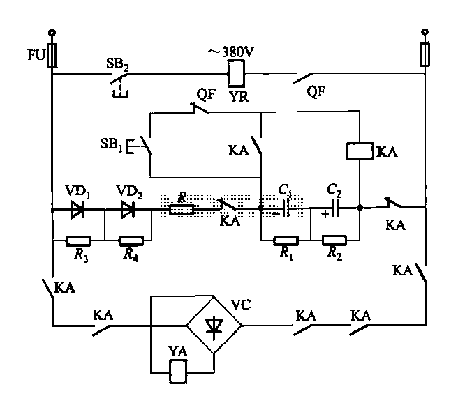
The DW15-200-630A breaker solenoid is a DC solenoid designed for short-time operation. The DK-1 control box utilizes an AC power switch to manage the electromagnet circuit, as depicted in Figure 6-7. The DK-1 type electromagnetic control box includes several...

A hydrophone is a device similar to a microphone, designed specifically for use in underwater environments. When utilized to capture sound in air, its effectiveness diminishes. A hydrophone operates by converting sound waves into electrical signals, making it an essential...
This circuit is fundamentally similar to the channel LED sequencer, with the enhancement of solid-state relays for controlling AC lamps. The relay depicted in the diagram is a Radio Shack 3 amp unit (part no. 275-310), which requires 1.2...
This is an astable multivibrator (oscillator) circuit using a CMOS inverter. The circuit employs the CD4007 or MC14007 integrated circuit. The operating frequency range of this circuit is not specified. The astable multivibrator circuit utilizes CMOS technology to create a...