
mini fm transmitter circuit

This mini FM transmitter circuit utilizes two 2N2222 transistors as the active components for amplification and oscillator functionality. The transmitter operates within the FM band, specifically between 80 MHz and 130 MHz, making it suitable for short-range audio transmission. The voltage-controlled oscillator (VCO) is crucial for modulating the frequency based on the audio input. The audio signal is fed into the base of the second transistor (Q2), which modulates the oscillator frequency, allowing the transmitted signal to carry the audio information.
The inductor (L1) and capacitor (C6) form a resonant tank circuit that determines the operating frequency of the oscillator. The design encourages the use of simple materials, such as 24-gauge enamel wire, for constructing the inductor, which is wound around a pencil to achieve the desired inductance. The construction technique emphasizes ease of assembly and accessibility for hobbyists.
The antenna is also a critical component, as it facilitates the radiation of the RF signal. The specified length of 8-12 inches is essential for ensuring that the antenna is resonant at the operating frequency, thus enhancing transmission efficiency. The careful design of the circuit, including the adjustable resistor R6, allows for fine-tuning of the input signal level, ensuring optimal performance.
Overall, this mini FM transmitter circuit exemplifies a straightforward yet effective design for short-range audio transmission, adhering to regulatory standards while remaining accessible for experimentation and learning in electronics.This ambit is a simple two transistor (2N2222) mini FM transmitter. No authorization is appropriate for this transmitter according to FCC regulations apropos wireless microphones. If powered by a 9 volt array and acclimated with an antenna no best than 12 inches, the mini fm transmitter will be aural the FCC limits.
The microphone is amplified by Q1. Q2, C5, and L1 anatomy an oscillator that operates in the 80 to 130 MHz range. The oscillator is voltage controlled, so it is articulate by the audio arresting that is activated to the abject of Q2. R6 banned the ascribe to the RF section, and it`s amount can be adapted as all-important to absolute the aggregate of the input.
L1 and C6 can be fabricated with wire and a pencil. The inductor (L1) is fabricated by ambagious two pieces of 24 barometer cloistral wire, laid ancillary by side, about a pencil six times. Remove the braid you accept formed and alleviate the two coils afar from anniversary other. One of these coils (the bigger attractive of the two) will be acclimated in the catchbasin circuit, and the added can be acclimated in the abutting one you build.
The antenna for mini fm transmitter (24 gauge wire) should be soldered to the coil you made, about 2 turns up from the bottom, on the transistor side, and should be 8-12 inches long. To make C6, take a 4 inch piece of 24 gauge insulated wire, bend it over double and, beginning 1/2 ³ from the open end, twist the wire as if you were forming a rope.
When you have about 1 ³ of twisted wire, stop and cut the looped end off, leaving about 1/2 ³ of twisted wire (this forms the capacitor) and 1/2 ³ of untwisted wire for leads. 🔗 External reference
Related Circuits
This Schmitt trigger circuit is emitter coupled and provides a simple comparator action. The 2N3069 JFET places very little loading on the measured input. Schmitt trigger, emitter coupled, simple comparator, 2N3565, distinct hysteresis loop. The described circuit utilizes an emitter-coupled...

This simple Christmas LED lights decoration circuit allows for the creation of an 18 LED flasher to adorn a Christmas tree. The circuit incorporates white, blue, and red LEDs that flash in a festive pattern. The circuit is designed to...

The circuit includes automatic exit and entry delays, a timed bell cut-off, and a system reset feature. It accommodates both normally-open and normally-closed switches, making it compatible with standard input devices such as pressure mats, magnetic reed contacts, foil...
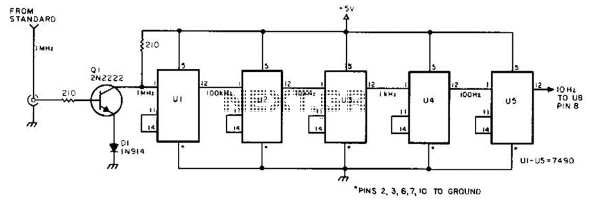
This circuit is designed to be driven by a 1-MHz standard signal with an amplitude of several volts. The components U1 through U5 are 7490 decade counters/dividers, providing a division ratio of 100,000:1. It is possible to tap off...
This circuit is an adjustable voltage reference circuit, which serves as a voltage source that provides a voltage greater than that of the reference diode. High precision applications that operate over an extended temperature range necessitate a restriction on...
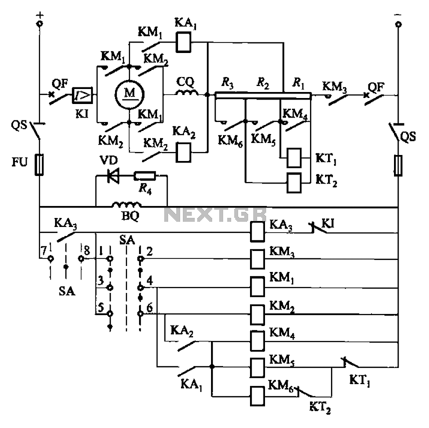
The circuit depicted in Figure 3-201 includes two starting resistors, with one controlled by a time relay. A master switch (SA) is utilized to manage the motor's reversing operation. The circuit incorporates a reverse braking mechanism, which is automatically...