
120VAC Lamp Chaser circuit

The circuit operates by utilizing the solid-state relay to switch AC lamps on and off in synchronization with a sequence determined by the LED indicators. The relay's low activation voltage (1.2 volts DC) makes it suitable for integration with various low-voltage control circuits, ensuring compatibility with microcontrollers or other logic devices that can output this voltage level.
When designing the circuit, the 360-ohm resistor plays a critical role in limiting the current flowing through the relay's activation circuit. Given a 9-volt supply, Ohm's law (V = IR) dictates that the maximum current through the resistor can be calculated as follows:
I = V/R = 9V / 360Ω ≈ 0.025A or 25mA.
This current is well within the operational limits for most low-power control applications. However, it is essential to confirm that the relay's internal LED can operate effectively with this current level, ensuring reliable performance without risk of damage.
The solid-state relay itself is designed to handle up to 3 amps of AC current, making it suitable for controlling standard household lamps or other light fixtures. The use of solid-state components provides advantages over traditional electromechanical relays, including faster switching times, longer operational life, and reduced electromagnetic interference.
In summary, this circuit effectively combines the functionality of an LED sequencer with the robust capabilities of solid-state relays, providing a reliable method for controlling AC lamps in a sequenced manner. Careful consideration should be given to component ratings and specifications to ensure optimal performance and safety in the final application.This circuit is basically the same as the channel LED sequencer with the addition of solid state relays to control the AC lamps. The relay shown in the diagram is a Radio Shack 3 amp unit (part no. 275-310) that requires 1.2 volts DC to activate. No current spec was given but I assume it needs just a few milliamps to light the internal LED. A 360 ohm resistor is shown which would limit the current to 17 mA using a 9 volt supply.. 🔗 External reference
Related Circuits
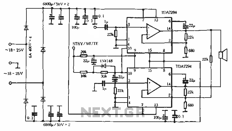
Europe's leading SGS-THOMSON STMicroelectronics recently introduced a new power integrated amplifier, the TDA7294, to the Chinese mainland market. This amplifier, characterized by a cold and hard tone, is particularly suited for Hi-Fi applications such as home theaters and active...
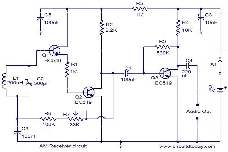
The following circuit illustrates an AM receiver capable of operating within the frequency range of 550 to 1100 KHz. Features include adjustments for sensitivity and selectivity of the circuit. The AM receiver circuit designed for the frequency range of 550...
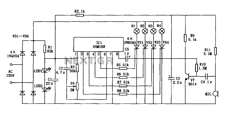
Family karaoke lighting design incorporates various methods for circuit control. The control circuit described here features a four-way light output with loop jumping and speed control capabilities. A microphone detects the acoustic signal strength, allowing the lights to jump...
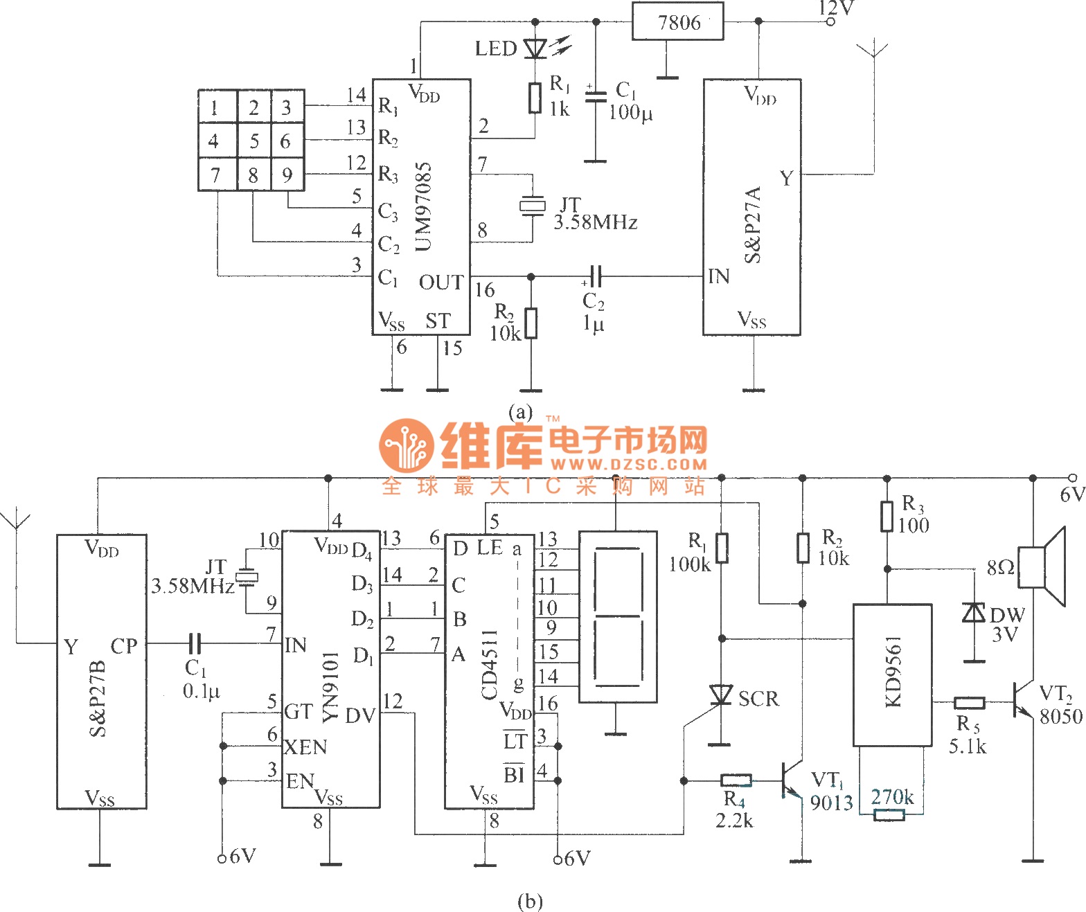
It utilizes a DTMF encoder output, which generates a dual-tone multi-frequency coded signal to modulate the transmitted carrier frequency. This configuration allows for the formation of a DTMF-encoded radio paging system. The circuit incorporates a DTMF encoding chip, UM97085,...
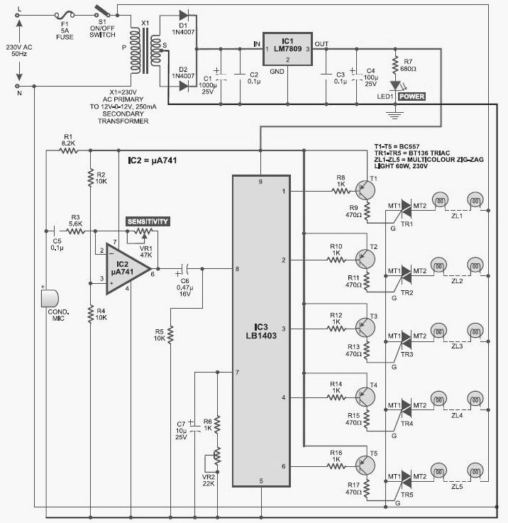
This light chaser circuit, which functions as a music-operated lighting effect generator, consists of five sets of 60W bulbs arranged in a zig-zag configuration. The light chaser circuit is designed to create dynamic lighting effects that synchronize with music, enhancing...
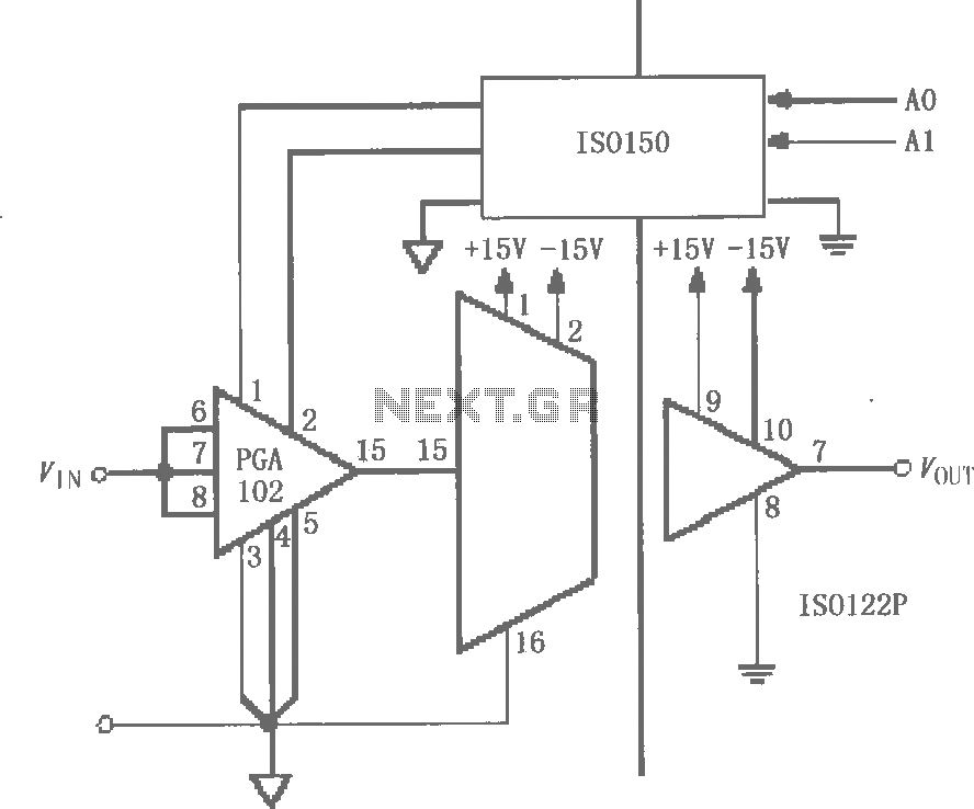
The circuit features grounds ISO122/124 and PGA102, with ISO150 forming a gain programmable channel isolation circuit. The input signal VIN is amplified by the instrumentation amplifier PGA102 to ISO122P, which then outputs VOUT from the isolation amplifier ISO102P. Two...