
A common car inverter circuit diagram and working principle
The car inverter circuit serves the essential function of converting direct current (DC) from the vehicle's battery into alternating current (AC) suitable for powering various electronic devices. The input voltage range of DC 10V to 14.5V corresponds to the typical voltage levels found in automotive batteries, which can vary depending on the vehicle's state of charge and load conditions.
The output specifications indicate that the inverter generates AC voltage in the range of 200V to 220V, with a permissible deviation of 10%. This output is designed to match the voltage levels required by standard household appliances and electronic devices. The output frequency is maintained at 50Hz, with a tolerance of 5%, which aligns with the frequency used in most countries for AC power supply.
The inverter's output power capability ranges from 70W to 150W, making it suitable for a variety of applications, including charging mobile devices, powering small appliances, and operating tools. The conversion efficiency exceeding 85% signifies that the inverter operates effectively, minimizing energy loss during the conversion process.
The operating frequency of the inverter, which ranges from 30kHz to 50kHz, is crucial for the performance of the pulse width modulation (PWM) technique employed in the circuit. PWM allows for the regulation of the output voltage and power by varying the width of the pulses in the output waveform. The use of integrated circuits such as the TL494 or KA7500 is prevalent in these designs due to their reliable performance and ease of implementation in PWM control applications.
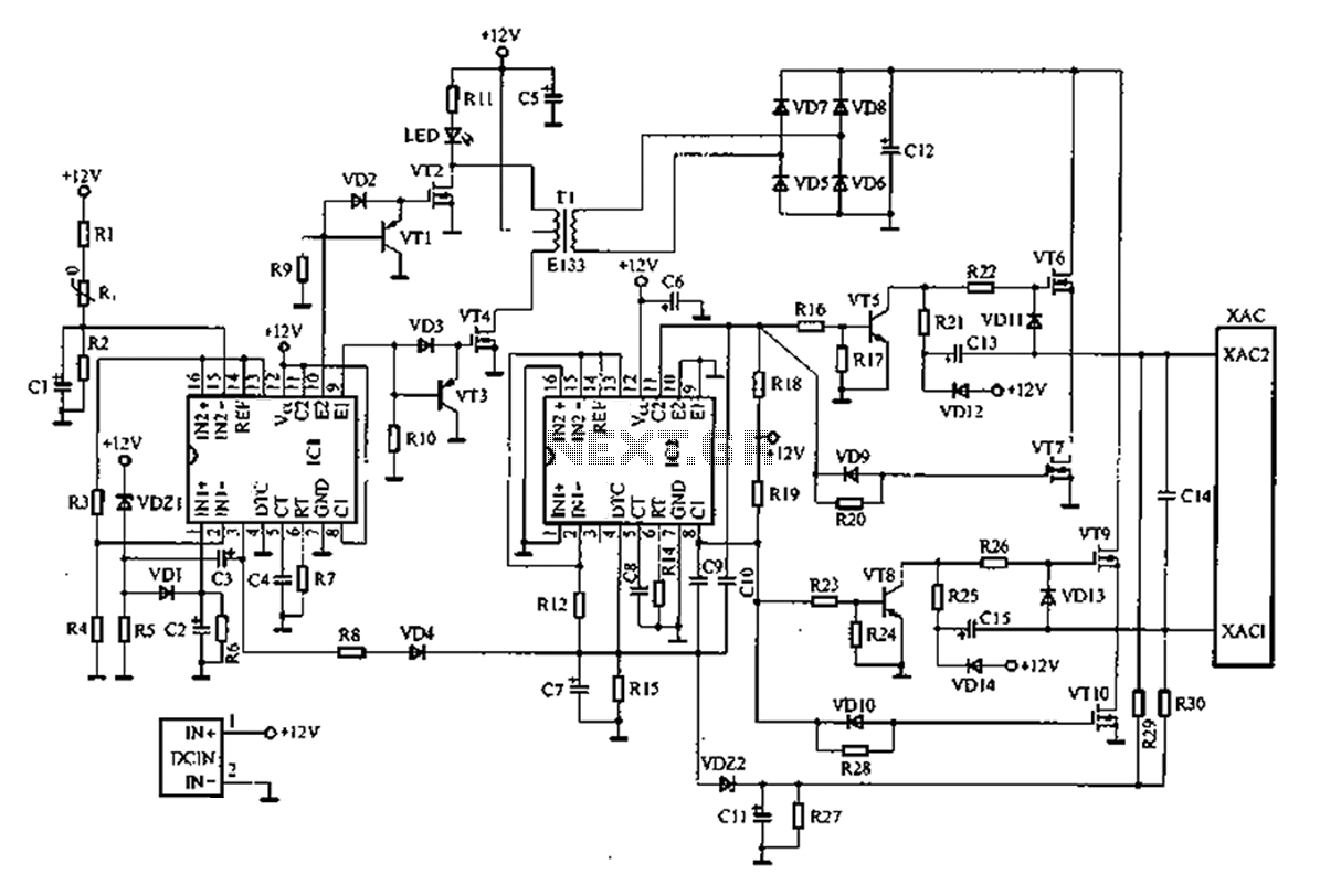
In summary, the common car inverter circuit is a vital component for converting vehicle DC power to usable AC power, with specifications tailored to meet the needs of various electronic devices while ensuring efficient operation. The schematic representation in Figure 1 serves as a visual guide for understanding the circuit's configuration and functionality.A common car inverter circuit and working principle Car Inverter indicators: Input voltage: DC 10V ~ 14.5V; Output Voltage: AC 200V ~ 220V 10%; Output frequency: 50Hz 5%; Outpu t power: 70W ~ 150W; conversion efficiency: more than 85%; the inverter operating frequency: 30kHz ~ 50kHz. Currently on the market sales of the largest, the most common car inverter output power of 70W-150W, the inverter circuit mainly uses TL494 or KA7500 chip-based pulse width modulation circuit.
One of the most common car inverter circuit schematic shown in Figure 1.
Related Circuits
The function of the sound level display circuit is to enhance the appearance of an amplifier circuit or a radio player. It provides an impressive visual representation of audio levels. The sound level display circuit serves as a visual indicator...
The MICRF112 is a high-performance, user-friendly, single-chip ASK/FSK transmitter integrated circuit (IC) designed for remote wireless applications within the 300 to 450 MHz frequency band. This transmitter IC features a true data-in, antenna-out configuration. The MICRF112 excels in three...
Most thefts occur after midnight when individuals enter the second phase of sleep known as paradoxical sleep. An energy-saving circuit has been designed to deter thieves by illuminating potential entry points, such as the kitchen or backyard, around 1:00...
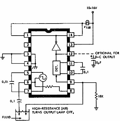
This electronic liquid detector circuit diagram utilizes the ULN2429A monolithic bipolar integrated circuit, which is designed to detect the presence or absence of various types of liquids. The detection mechanism involves comparing the resistance of a probe immersed in...
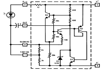
The schematic diagram below illustrates a typical 1.5V flasher circuit using the LM3909. The LM3909 is a monolithic oscillator designed specifically for flashing Light Emitting Diodes (LEDs). The LM3909 flasher circuit operates at a low voltage of 1.5V, making it...
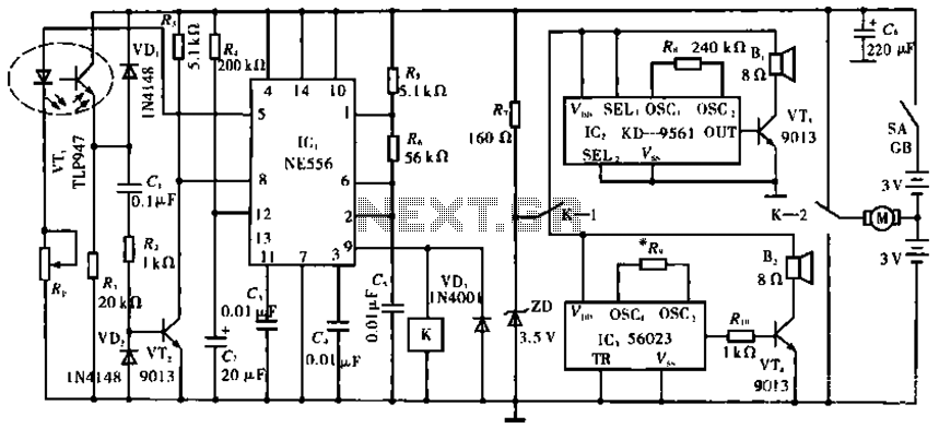
The circuit operates with VT1, which is an integrated infrared receiver, utilizing a red-emitting diode for perimeter triode reception. IC1 (NE556) functions as a dual timer, with R5, R6, and C5 forming an oscillation circuit that generates a frequency...