
Stereo VU Meter Circuit LM3915 IC
The sound level display circuit serves as a visual indicator of audio signal levels, improving the aesthetic appeal and functionality of audio devices such as amplifiers and radio players. Typically, this circuit utilizes light-emitting diodes (LEDs) or liquid crystal displays (LCDs) to represent the amplitude of the audio signal in real-time.
The circuit usually consists of several key components: an audio input stage, a signal processing unit, and the display unit. The audio input stage often comprises a microphone or line-level input to capture the audio signal. This signal is then filtered and amplified to ensure that it is suitable for further processing.
The signal processing unit typically includes an analog-to-digital converter (ADC) if the display is digital, or it may utilize analog components such as rectifiers and peak detectors for analog displays. This unit processes the audio signal to extract relevant information about its amplitude, which is then used to control the display.
In the display unit, LEDs or LCDs light up in response to the processed audio signal levels, providing a visual cue that corresponds to the loudness of the sound being played. The design may include multiple LEDs arranged in a bar graph format, where each LED represents a specific range of audio levels, or a single multi-segment display that indicates the current level of the audio signal.
The circuit can be powered by a standard DC power supply, and careful consideration should be given to the power requirements of each component to ensure reliable operation. Additional features such as adjustable sensitivity or peak hold functions can also be implemented to enhance the circuit's functionality.
Overall, the sound level display circuit not only enriches the user experience by providing a visual representation of audio levels but also improves the overall design and usability of audio equipment.The function of sound level displayer circuit to improve the out look of your amplifier circuit or your Radio player. Actually this gives an unbelievable .. 🔗 External reference
Related Circuits
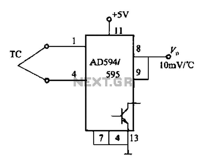
The AD594/595 series describes the relationship between output temperature and thermocouple voltage. For the AD594, the output voltage (Vo) is calculated using the formula: Vo = (VoJ + 16 μV) × 193.4 (mV), where VoJ represents the output voltage...
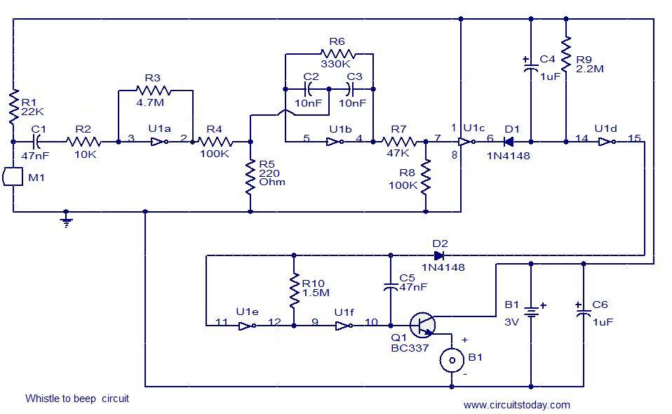
This simple circuit produces a beeping sound that lasts for approximately 3 seconds whenever a whistle is made. The CMOS Hex inverter CD4049 serves as the core component of this circuit. Among the six inverters in the CD4049, U1a...
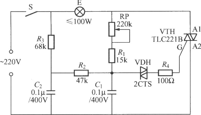
To address the lag and light transition issues, a Triac dimming light circuit featuring a dual time constant can be employed. This circuit enhances the resistor-capacitor network formed by R3 and C2. The reduced charge on capacitor C1 can...
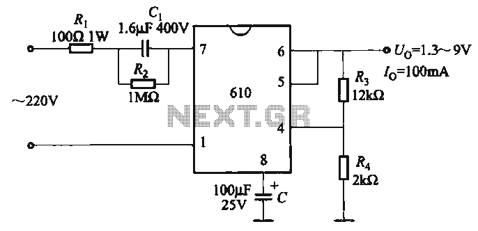
The output voltage can be calculated as follows: U = 1.3 (1 + R3 / R4) (V), where R3 and R4 are part of an adjustment potentiometer, allowing for a continuously adjustable output voltage. The described circuit involves a voltage...
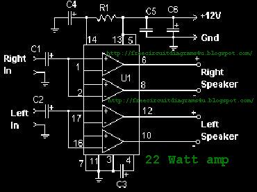
The circuit-delay relay for speakers serves as a delay mechanism that prevents the immediate activation of speakers when the amplifier is powered on. This feature is designed to protect the speakers from potential damage caused by sudden power surges....
The original scale on the voltmeter ranged from 0 to 30 volts. A new scale was created by removing the old scale from the meter and scanning it into a graphics editing software on a computer. The old numbers...