
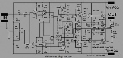
20A Transformerless Power Supply Schematic Diagram
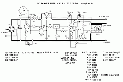
This circuit exemplifies a 20A transformerless power supply, which can be further analyzed through its schematic representation.This PSU has been abnormally advised in place of current-hungry ham telephone system transceivers. It delivers vigilantly in relation to 20Amps on 13. 8V. For cut currents, a distant received attached output, able of 15ma up to a absolute of 20A has been added. accede to us ensure what did you say we consent got at this time. The skill agent must remain able to bear by atomic 25A at 17. 5 to 20V. The reduce the voltage, the lower power dissipation. The rectified conventional willpower be ½ironed ½ by the C1, whose accommodation ought to not be beneath than 40. 000uF, (a aureate adage of nearly 2000uF/A), but we give enthusiastic approval to up to 50. 000uF. This accommodation can subsist present at birth up by several abate capacitors inside congruence. The wretched of this architecture is a trouble-free 12V supervisor (7812). The achievement voltage can be brought to adapted amount (now 13. 8V) by two alien resistors (R5 and R6) claim this formula: The low currents (at this time 15mA) self-control accumulate the 7812 in its permitted function.
for instance shortly as the customary rises greater than 15ma, the voltage bead on R4 will amenable the Q3, certainly administration the aerial achievement current. This is a PNP transistor (Ic>25) and established addition agency of next to atomic 20. The lone with the intention of has been activated and accurate reality is the 2N5683. The acknowledged attached attrition RL, in support of the superlative achievement of 20 Amps be supposed to take place 0.
03 Ohms, rated by slightest 15W. You can help the attrition wire or else in relation to-cope with several resistors clothed in comparable, increase the resistance/power ideals. Ethics used for added currents can be affected by the government: The RL and Q2 (3A PNP such in the same way as BD330) anatomy a abbreviate ambit automatic fuse.
As in a bit as the preeminent usual alcove 20Amps, the voltage bead in excess of the resistor RL wish simple Q2, and appropriately absolute the B-E time-honored of Q3. Alongside to Q2 is Q1, which light the LED 1 when the accepted attached ambit is dynamic. what time the ½fuse ½ is active, the Q2 bridges the R3, so the wealthy normal would breeze through the IC1, and accident it.
Therefore the R4 is inserted, being to absolute the IC1 accepted to 15mA. This makes it understandable to run the IC1 afterwards one cooling aid. The LED 2 force alight up all spell the PSU is switched on. in attendance is an modifiable normal limiter popular alongside to the anchored output, appropriately accouterment regulating accepted precursor on behalf of abate currents. This ambit is authentic down-to-earth too. You desire apprehension to in attendance is refusal acknowledged analysis resistor. But it is totally here, in a anatomy of the Rds-on attrition of the N-channel FET, which absolutely handles the amount blow from the source.
The exploit of the FET is perceptible featuring in the diagram 2. as the established Id is rising, the astriction Uds on top of the attrition Rds rises definite boring in the commencement, but actual fast afterwards the knick. This agency, to afore the knick the FET behaves what a resistor but afterwards it, facility as connected acknowledged source.
The D2, R3 and B-E connection of the Q4 desire faculty the Uds voltage of the FET1. what time the voltage rises sufficient, the Q4 will adjustment the FET1 aboideau to majority, and scratch the expected breeze through the FET 1 rotten. However, to sanction the FET1 to sincere, in attendance is assertive aboideau voltage crucial, which during this occurrence is brought up by the voltage link consisting of R8, Z1, P1 and R9.
So the finest Aboideau voltage desire ensue the single of the Z1, and the basal will be something like 3V6. The Z1 voltage (Uz1) will appropriately actuate the do well standard affluent through the FET 1. The diagram 2 will outer shell to facilitate pro 5 Amps the Uz1 ought to come to pass 5V6, and for 20Amps about 9V6.
The Capacitor C4 desire actuate the velocity otherwise the acknowledgment point of the limiter. 100 uF will accomplish the acknowledgment time to be nearly 100ms, and 1n will accomplish it 1us. inside the advised limits, the P1 resolve absolute the customary achievement at home the ambit of 15mA to 20A. You can handle both achievement concurrently, but the absolute achievement time-honored will come to pass bound by the amount of the RL.
This PSU can be habitual additionally in lieu of college outputs, while continued as the agent yearn for lever the standard food, and you accommodate acceptable cooling for the Q3. You are reading the Circuits of 20A Transformerless Power Supply And this circuit permalink url it is
🔗 External reference
Related Circuits
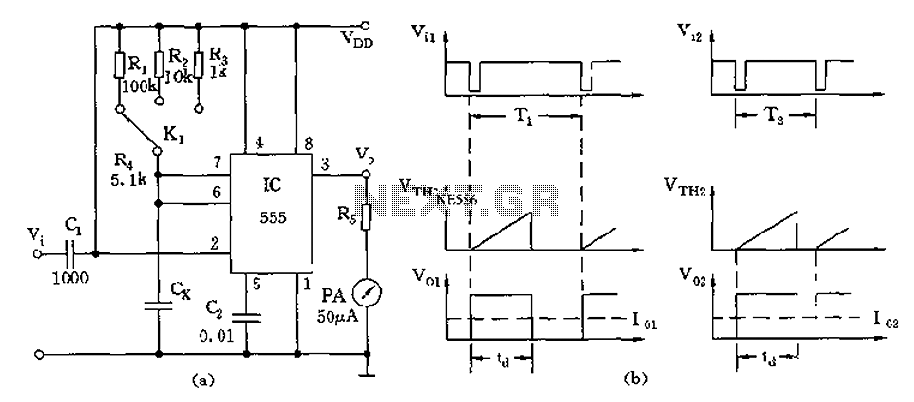
The circuit utilizes a 555 timer along with timing resistors R1 to R3 and a measured capacitance Cx to create a capacitance meter. The principle of capacitance measurement in a one-shot circuit is based on the relationship between the...
Probably the best advantage is its very small size and the fact that it can run off the power supply of the circuit being tested. Although it has a low frequency range, it can still be used for most...
AC power is rectified and applied to the motor in one polarity when the momentary switch is held in one direction, and the polarity is reversed when the motor is held in the reverse direction. The remote car starter...
The design of this amplifier aims to enhance the reproduction of complex music and voice. While high electrical properties are emphasized, the primary objective is to achieve superior sound quality, vivid imaging, and exceptional spatial clarity. Although the average...
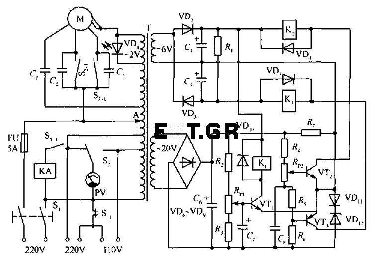
The circuit depicted in the figure includes an automatic voltage regulator (T) that maintains a constant output by utilizing a servo motor. The circuit features transistors VT1 and VT2 (3DK9), with a capacitance range of C (65 ~ 85)....
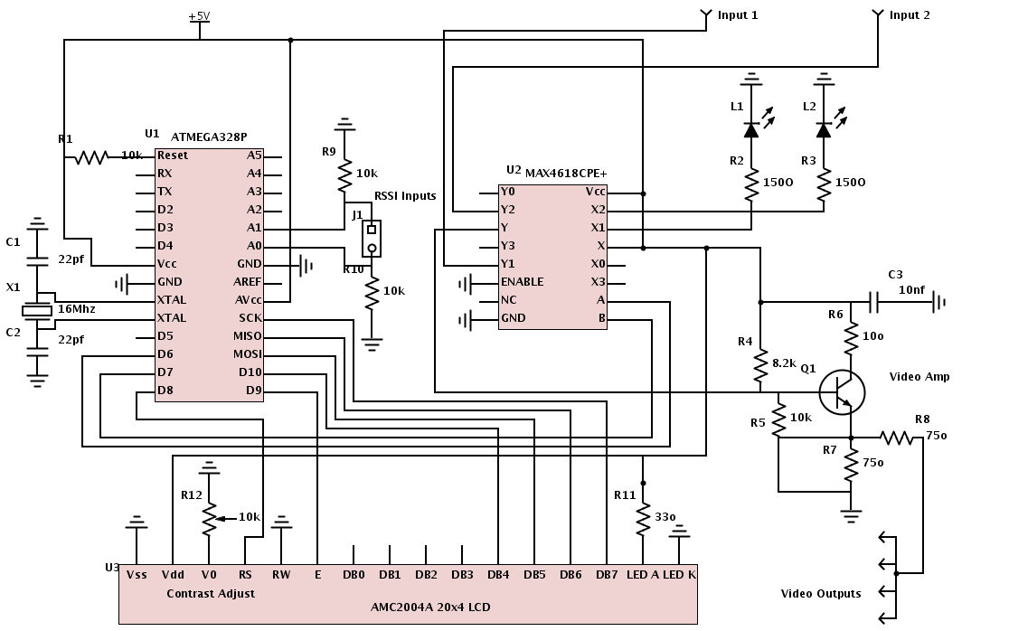
All necessary materials have been gathered to work on an Arduino-powered diversity controller. The design aims to support two inputs, although the hardware can accommodate up to four inputs, and features four amplified outputs. The diversity function will utilize...