
A digital Clock made from 74 logic. - Google Project Hosting
The electronic circuit design described involves a multi-stage power supply system tailored for a low-power application, specifically for a digital watch utilizing seven-segment displays. The architecture includes a battery backup mechanism to ensure uninterrupted operation during power outages, while the logic ICs are selected from the HS family for their low power consumption characteristics. The use of a CR2032 battery is optimal due to its compact size and voltage compatibility. The seven-segment displays, configured as common anode, require careful voltage management due to the inherent voltage drop across the series-connected LEDs.
The implementation of a BCD driver/decoder, specifically the 74LS74, allows for effective interfacing between the digital logic and the display. However, the driver’s power supply requirements necessitate additional voltage regulation. A multi-tier power supply design is employed, with a 7805 voltage regulator stepping down the 12V supply to 5V for the display drivers, while an LM317 regulator provides 3.3V for the logic components. The design includes protective diodes to prevent reverse polarity from damaging the circuit.
The clock generation circuit is a fundamental component of the design, utilizing a crystal oscillator to provide a stable frequency reference. The division of the clock signal to achieve the required 1/60Hz output is accomplished through a series of counters, facilitating accurate timekeeping. The inclusion of push-button controls allows for manual adjustments to the time display, enhancing user interaction.
Overall, this circuit design emphasizes low power consumption, reliability, and user-friendliness, making it suitable for battery-operated digital watches. The careful selection of components and the thoughtful arrangement of the circuit elements contribute to the overall efficiency and functionality of the device.Both specifications were contradictory, a big display would need lot`s of power, with battery backup he wish to use the smallest battery for the longest time. The solutions was to divide power supply for the logic and displays. The battery would only backup the logic, that should be of the HS family because of it`s power consumption drops to almos
t zero when running on a low clock frequency. These ICs run down to 2V so the battery could be a CR2032. The next step was to find the display, a seven segments display looks cool for a watch. I got four 57mm Common Anode displays in a local store. I made some measurements on the display and find that the voltage drop over each segment about 7V @15mA. The datasheet also showed this numbers. The big voltage drop happens because each segment has for LEDs in series. Here is a picture of some of the important info in the datasheet. With a display at hands a driver is needed to interface with the logic. A BCD driver/decoder would help a lot, decoding the binary input from the logic to the segment to lit.
A open collector driver must be used because the displays require a big supply voltage to overcome the diode drops. A minimum of 15mA per segment, these displays can handle up to 40mA. The only display driver/decoder that i could buy that meet these specs was a 74LS74. The problem is that this as this is a LS series chip it needs a 5V supply and consumes a lot of power.
So a 3 power supply was needed that would not need battery backup. The internal circuitry of the 7447 is just combinational logic. The clock circuit is just a bunch of counters run by a clock of 1/60Hz. Is a finite state machine made from sequential logic. The kind of state machine used is a Moore machine. These stuff is a lot better explained on other places, just Google it. The counting circuit is on the picture, from the left to the right are the hour decade and units counters, decade and units minutes counters. The outputs are connected to the displays drivers. The only input is the clock since this just count forward. Now we need to generate that 1/60Hz clock. I chose to base it on a crystal oscillator that will be explained shortly, let`s just say that it outputs a precise 32768Hz square waveform (32768 = 215).
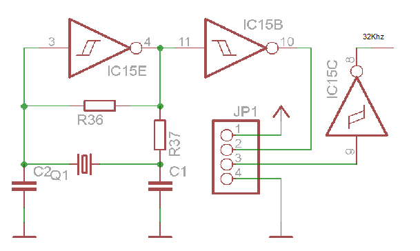
To divide that clock I used counters, a 14 bit counter divide the clock to 2Hz first. Then a 12 count and a decade counters make the 1/60Hz clock. Two push-buttons can bypass the clock in some parts of the circuit making the output frequency be 256Hz and 4. 26Hz. The 4Hz output is useful to adjust the minutes ( the minutes digit changes four times per second). And the 256Hz output to adjust the hour (hour digit changes four times per second, 256/60=4. 267). The crystal oscillator looks simple but it is tricky. It is a Pierce oscillator, the problem I had was to find the correct capacitors to get the exact frequency output.
My home tools didn`t had enough resolution to check the frequency. Don`t get me wrong, the crystal showed as running at 32. 76kHz at the breadboard ( I know a breadboard is not the place for this kind of circut, but it was only a test), but the clock was drifting about 1 min. per hour. So left a connection on the board for a better clock reference, and with a jumper the on board oscillator could be used (more on that later).
After all this the power supply will come with easy. The requirements are a 3V with battery backup (HS ICs), 5V (LS display drivers), and 12V unregulated (12V does not waste to much energy on the displays, and I also one in my junk bin) power rails. A diode on the input protects the board from a inverted polarity supply. This go directly to the displays. The 12V are regulated to 5V by a 7805, and again to 3V3 by a LM317. The output of the LM317 and the battery are connected by two diodes to the power line, this way the battery backs up when the 317 is off.
Since this will go to the DAELE I tough that a row of "programable" displays would be nice. I say programmable because you can chose witch display to lit based on the soldered on the board. Quoting Dave Jones `Soldering is my programming language`. Testing the current consumed by one of the counters to check if it is on specs. On the left is the current measured with some unused inputs unconnected, the picture on the left it`s the current of the same circuit but now with the unused inputs grounded. Low power design is all about taking care of this kind of stuff. About the problem with the Crystal oscillator, I have fixed that. A capacitor get`s replaced by a variable-cap, this way the oscillation frequency can be shifted lightly.
With a good signal generator and a scope you can adjust the clock (Just generate a 32. 768Khz waveform and check if the oscillator stays in phase). I changed the IC also, the old one didn`t locked at 32Khz on every power up. 🔗 External reference
Related Circuits
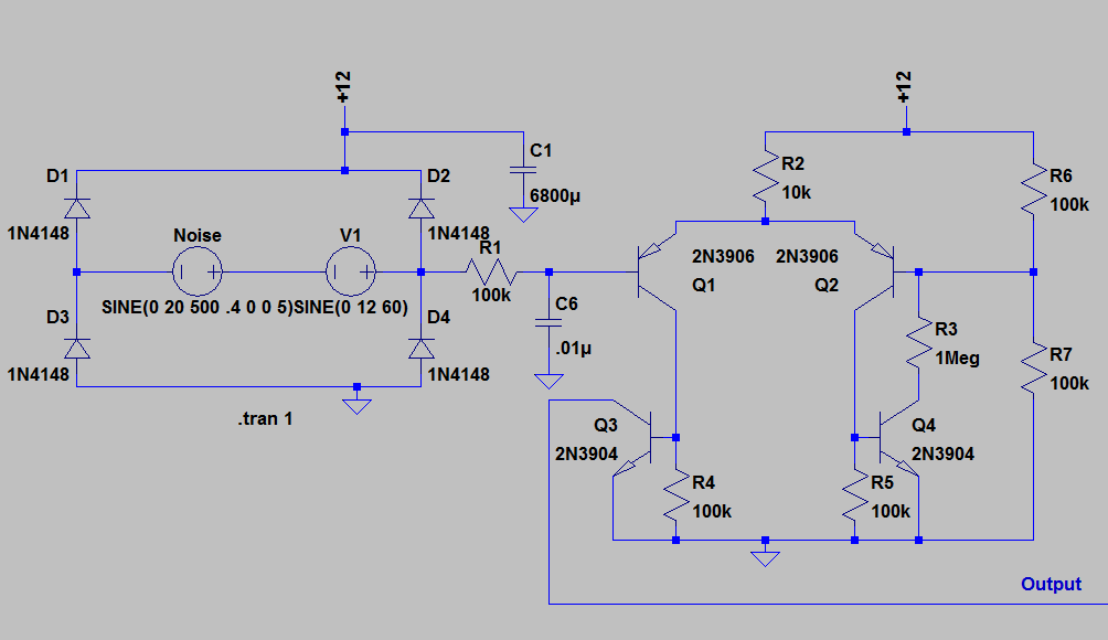
If you have been following on Twitter, you might have seen a tweet about a "Transistor Clock" kit that allows for the construction of a wall clock using 194 discrete transistors and numerous other components. This kit has been...
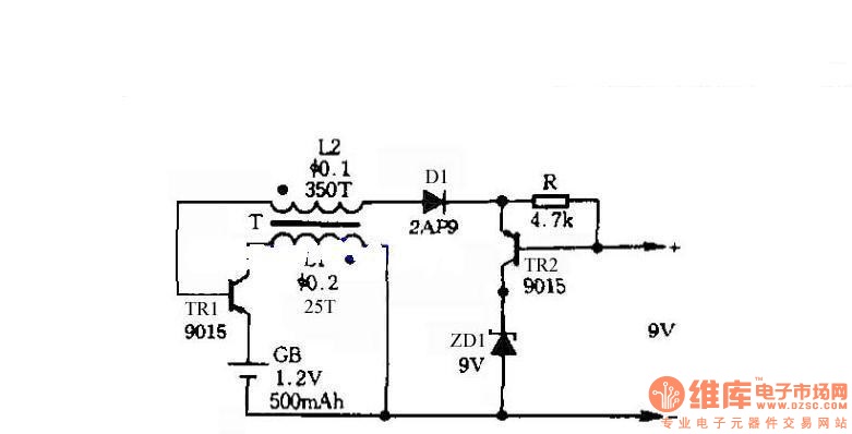
The circuit does not require a separate power switch or transformation to control the switches on the table. It offers advantages such as low power consumption, stability, reliability, and no impact on instrument accuracy. The transformer T in the...
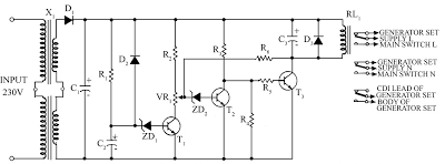
Due to the energy crisis, load shedding has become a common issue in several countries. Sudden power fluctuations, surges, and high voltage can damage sensitive household appliances such as TVs, VCRs, VCPs, and music systems. This circuit offers protection...
The Thor project commenced at the High Voltage Institute of HUT (Helsinki University of Technology) in January 1999. Dr. Martti Aro oversees the project, while Marco Denicolai is responsible for its development and implementation. This project involves the analysis,...
TL072 is a low-noise JFET input operational amplifier characterized by features such as a common-mode input voltage range, high slew rate, operation without latch-up, compensated internal frequency, high input impedance at the JFET input stage, low noise, low total...
The following circuit diagram depicts a variable power supply controlled by a PIC microcontroller. An LCD display is utilized to show the actual output current and voltage values. This digital power supply incorporates a push-button switch to adjust the...