
auto changeover from generator to mains
The circuit designed for protecting household appliances from power fluctuations and surges incorporates several key components that work together to ensure safe operation. The primary function of this circuit is to monitor the incoming line voltage and respond accordingly when it exceeds a predetermined threshold. This is accomplished using a Zener diode (ZD4), which is configured to break down at a specific voltage level. When the voltage crosses this threshold, ZD4 conducts, triggering transistor T2 to enter a conductive state. This action effectively turns off transistor T3, leading to the de-energization of the relay that controls the connection to the mains supply.
In addition to the immediate response to over-voltage conditions, the circuit includes a delay mechanism implemented around transistor T1. This delay serves to protect the connected appliances from potential voltage surges that may occur when power is restored after a blackout or load shedding event. The delay can be adjusted by varying the capacitance of capacitor C2, allowing for customization based on the specific requirements of the connected appliances and the characteristics of the power supply.
The circuit also integrates a safety feature for generator operation. Portable generators, whether powered by petrol or kerosene, typically have a connection from the CDI (Capacitor Discharge Ignition) system. To safely stop the generator engine, this connection must be momentarily grounded, which is facilitated through a switch connected to the normally closed point of the relay. This ensures that the generator can be turned off safely without risking damage to the system.
To enhance the reliability and longevity of the circuit, two transformers are employed in series rather than a single transformer. This configuration helps distribute the load more effectively, reducing wear and tear on individual components. Additionally, a negative feedback resistor (R6) can be incorporated between transistors T3 and T4. This resistor, with a resistance value adjustable between 15 k-ohm and 100 k-ohm, helps to stabilize the circuit and prevent potential damage from voltage fluctuations, thereby ensuring consistent performance over time.
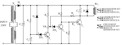
Overall, this circuit provides a robust solution for protecting sensitive electronic equipment from the adverse effects of power supply irregularities while also ensuring safe generator operation.Because of energy crisis Load shedding may be a common problem in several countries. Sudden power fluctuations, surge and high voltage may spoil sophisticated household appliances like TV, VCR, VCP and music system. This circuit provides protection against these problems and automatically changes the power supply from Generator output to mains sup
ply and also switches off the generator. This circuit is self explanatory. When lines supply voltage crosses the preset level, Zener diode ZD4 break down and thus transistor T2 conducts, T3 does not conduct, causing the relay to de-energise. Voltage surge at the time of power resumption is protected by the delay circuit around transistor T1.
All the portable petrol and kerosene generators have a connection from CDI. To stop the engine of the generator-set, this connection is to be grounded momentarily (through the switch). This lead is to be connected with the ground through the N/C point of the relay. Instead of the one transformer, two transformers are used in series to ensure better life of the unit.
Value of capacitor C2 can be increased or decreased for the variation of delay time. A negative feedback resistance, R6 (15 K-ohm to 100 k-ohm) can be incorporated between transistor T3 and T4 to overcome the damage that could be caused by voltage fluctuations. 🔗 External reference
Related Circuits
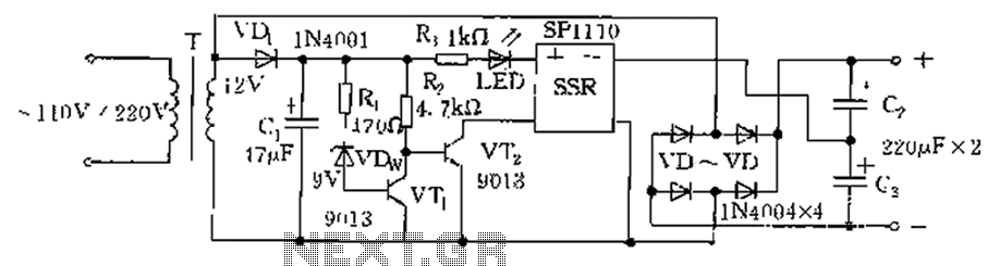
The circuit is automatically converted to a low-voltage configuration. A 220V AC supply is stepped down by transformer T. After this, the breakdown voltage of diode VDw causes transistors VT1 and VT2 to turn off, resulting in the solid-state...
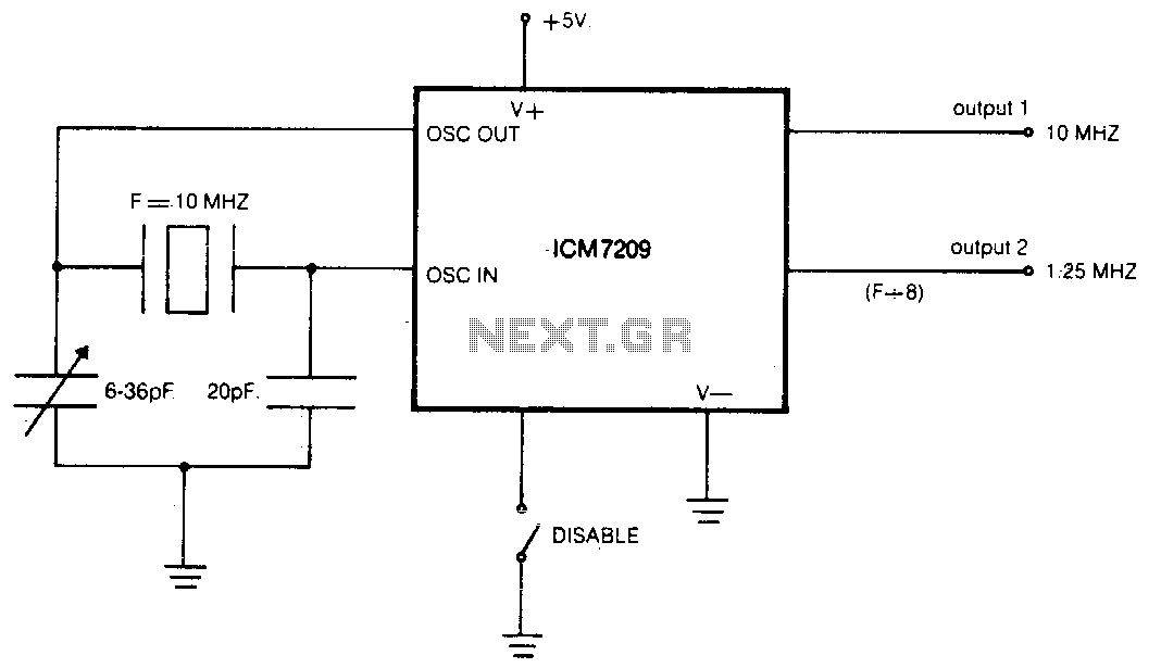
The CMOS IC directly drives five TTL loads from either of two buffered outputs. The device operates at up to 10 MHz and is compatible with bipolar, MOS, and CMOS technologies. The CMOS integrated circuit (IC) is designed to interface...
Many electronics hobbyists have encountered the situation where a project is being completed late at night and the mains supply fails. The cause of the failure, whether due to the electricity provider or personal oversight, is not significant. In...
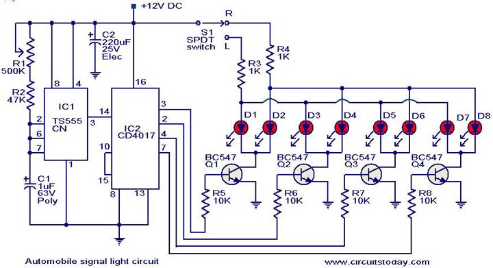
This is a simple circuit that can be used as a sequential signal light in automobiles. The circuit is based on two integrated circuits (ICs): a TS 555 CN CMOS timer IC and a CD4017 decade counter IC. The...
This circuit features a white LED-based emergency light that provides several benefits. It is exceptionally bright due to the incorporation of white LEDs. The light activates automatically when the mains supply is interrupted and deactivates when mains power is...

This circuit utilizes a NE555 timer and a CD4020B. When +12 Vdc is applied to the circuit, the output of IC2 is set low via C2, which activates the relay and IC1, functioning as a pulse generator. IC1 generates...
Warning: include(partials/cookie-banner.php): Failed to open stream: Permission denied in /var/www/html/nextgr/view-circuit.php on line 713
Warning: include(): Failed opening 'partials/cookie-banner.php' for inclusion (include_path='.:/usr/share/php') in /var/www/html/nextgr/view-circuit.php on line 713