
Subwoofer Amplifier Power Supply Circuit

The power supply circuit is engineered to deliver stable voltage and sufficient current to ensure optimal performance of the connected amplifiers. It typically consists of a transformer, rectifier, filter capacitors, and voltage regulation components.
The transformer steps down the mains voltage to the required secondary voltage of 30 to 35 V. The rectifier, often implemented using a bridge rectifier configuration, converts the AC voltage from the transformer into pulsating DC. This output is then smoothed by large filter capacitors, which reduce the ripple voltage to provide a more stable DC output.
For amplifiers demanding consistent performance during varying load conditions, additional voltage regulation may be integrated. This could involve linear voltage regulators or switching regulators, depending on the efficiency requirements and thermal management considerations.
Protection features such as fuses or circuit breakers can be included to safeguard against overload conditions, ensuring the longevity of both the power supply and the connected amplifiers. Furthermore, proper heat dissipation measures, including heat sinks or ventilation, are crucial for maintaining safe operating temperatures.
Overall, this power supply design is versatile and robust, making it suitable for a range of audio amplification applications. Although intended to power a 100-W low-frequency amplifier, this power supply should handle many mono or stereo amplifiers in the medium power range that require 30 to 35 V.
Related Circuits

The duration for which the circuit remains active is determined by the time required for the stored electrical current to leak back into the circuit, which keeps the transistor and the entire circuit energized. A resistor is present that...
This FM transmitter circuit employs four radio frequency stages: a VHF oscillator built around the transistor BF494 (T1), a preamplifier constructed with the transistor BF200 (T2), a driver using the transistor 2N2219 (T3), and a power amplifier based on...
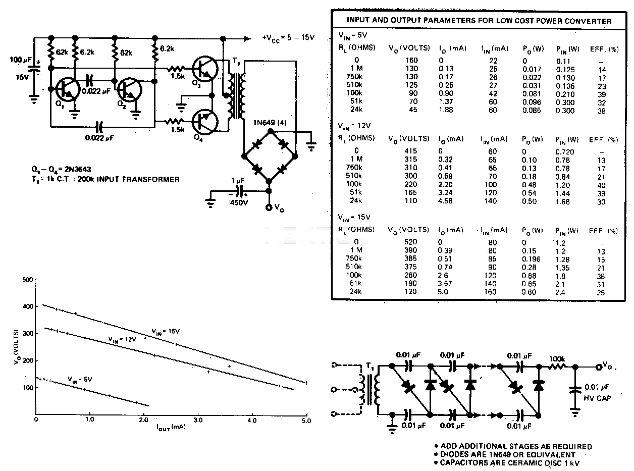
This circuit consists of an astable multivibrator driving a push-pull pair of transistors into the transformer primary. The multivibrator frequency should equal around 1 or 2 kHz. For higher DC voltages, voltage multipliers on the secondary circuit have been...
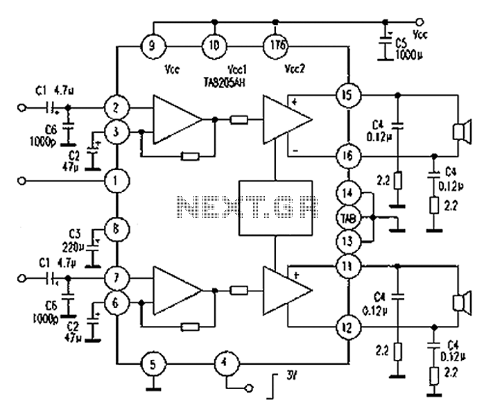
A Mitsubishi Pajero car audio system is experiencing a silent fault, while other features remain operational. The issue is traced to a damaged amplifier IC, specifically the TA8205AH. This integrated circuit, produced by Toshiba, is a dual-channel audio power...
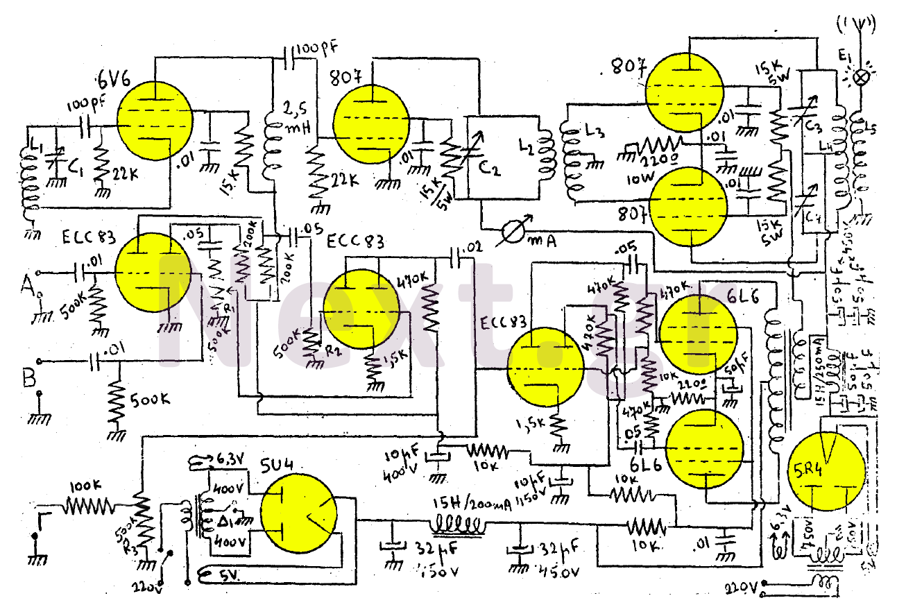
This transmitter consists of a 6V6 oscillator that excites an 807 buffer. The final stage includes two 807 tubes arranged in a Push-Pull configuration. The amplifier is built with three series-connected double-triodes (ECC83) and concludes with two 6L6 tubes...
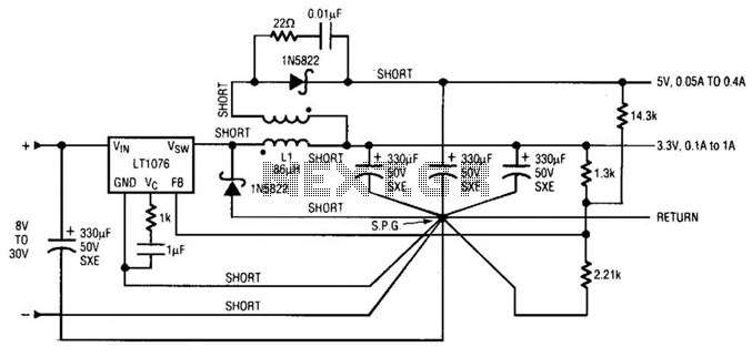
Input voltages can range from 8 V to 30 V. The load range for the 5 V output is from 0.05 A to 5 A, while the load range for the 3.3 V output is from 0.1 A to...