
Electronic Circuits Diagram
These collections serve as valuable resources for engineers, students, and hobbyists interested in electronics design and development. They encompass a wide range of topics, including basic circuit designs, advanced PCB layouts, and innovative project ideas that can inspire and educate users.
Typically, electronic schematics illustrate the functional relationships between electronic components, such as resistors, capacitors, transistors, and integrated circuits. Each schematic diagram is a graphical representation that indicates how these components are interconnected, allowing for a clear understanding of the circuit's operation.
Printed circuit board diagrams, on the other hand, provide a detailed layout of the physical arrangement of components on a PCB. These diagrams include information on the placement of components, routing of electrical connections, and specifications for manufacturing. Properly designed PCB layouts are crucial for ensuring signal integrity, minimizing electromagnetic interference, and optimizing thermal management within electronic devices.
In addition to schematics and PCB diagrams, these collections often feature a variety of electronics projects. These projects may range from simple circuits, such as LED blinkers and audio amplifiers, to more complex systems like microcontroller-based applications and IoT devices. Each project typically includes a description, schematic diagrams, component lists, and step-by-step assembly instructions, facilitating hands-on learning and experimentation.
Overall, electronic schematics collections represent an essential aspect of the electronics community, fostering collaboration, knowledge sharing, and innovation among enthusiasts and professionals alike.Electronic Schematics collections where they discuss about electronic circuits schematics, printed circuit board diagrams and electronics projects 🔗 External reference
Related Circuits
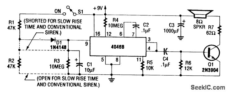
For a normal wailing tone, short D1 and leave R2 open. To achieve a fast rise and slow fall in frequency, include both D1 and R2. Utilizing a CD4046B with a diode-RC network as illustrated generates a siren tone...
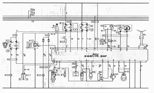
The following document contains information related to the electrical installation schematic diagram for the Volvo 440. It includes the wiring schematic for the Volvo 440, 460, and 480 series. The Volvo 440, 460, and 480 series vehicles feature a comprehensive...
Writing about multiple circuits in Marx, an entire new set has been discovered, referred to as "the" Marx Generator. There are diagrams available, along with a useful quote: "The main advantage of the Marx circuit configuration over a more...
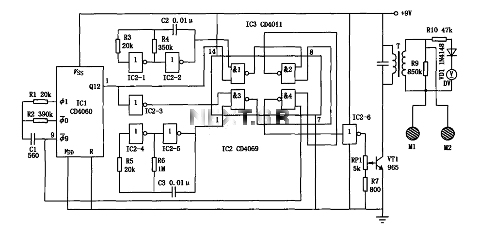
The electronic bio wave therapy instrument circuit is designed to generate a variety of complex frequency electrical signals. These signals can enhance the absorption of medication and provide direct therapeutic effects on specific body points. The electronic bio wave therapy...
A flip-flop is a bistable multivibrator. It is a circuit that has two output states and is switched from one to the other by means of input signals. A flip-flop serves as a fundamental building block in digital electronics, primarily...
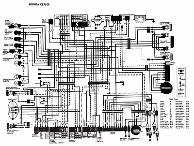
The following image illustrates the electrical wiring connection diagram for the Honda Motorcycle CB750F. It details the connections between various Honda components, including the right turn signal indicator light, oil pressure warning light, neutral indicator, high beam indicator, turn...
Warning: include(partials/cookie-banner.php): Failed to open stream: Permission denied in /var/www/html/nextgr/view-circuit.php on line 713
Warning: include(): Failed opening 'partials/cookie-banner.php' for inclusion (include_path='.:/usr/share/php') in /var/www/html/nextgr/view-circuit.php on line 713