
Arduino Based Current Sensor Circuit

The ACS712 current sensor operates by utilizing the Hall effect to detect the magnetic field generated by the current flowing through the copper conduction path. This allows for non-intrusive current measurement, which is particularly advantageous in applications where direct contact with the current-carrying conductor is impractical or unsafe. The device's linear output voltage is directly proportional to the measured current, facilitating easy integration with microcontrollers such as Arduino.
To implement the ACS712 in a circuit, it is essential to connect the IP+ and IP- pins in series with the load whose current is to be measured. The VIOUT pin provides an output voltage that varies with the current flow, which can be read by an analog input pin on the Arduino. The required filtering capacitors help to stabilize the power supply and the output signal, reducing noise and improving measurement accuracy.
The Arduino processes the output voltage from the ACS712 using a defined formula to convert the analog voltage reading into a current measurement. This calculated current can then be displayed in real-time on a computer screen via a serial connection, providing valuable insights into the performance of the monitored system. The use of software like Analog Demo allows for graphical representation of the current over time, enabling users to analyze trends and anomalies effectively.
In terms of accuracy, the ACS712 is designed to operate within specified limits, and its performance can be validated against known current sources, such as a microcontrolled battery charger. This validation process ensures that the system operates correctly and that the readings are reliable for the intended application. Overall, the ACS712 sensor presents a versatile and efficient solution for current sensing in various electronic applications.The main component used is the ACS712 sensor from Allegro MicroSystems to measure the current. It provides economical and precise solutions for AC or DC current sensing in industrial, commercial and communications systems. Located near the surface of the die of the device is a precise, low-offset, linear Hall sensor with a copper conduction path.
The device is not intended for automotive applications but is typically used in motor control, switched-mode power supplies, over current fault protection, load detection and management. This project uses one of the three models of ACS712. Other models can be chosen depending on the maximum measured current (5-20-30A). From its pin configuration, the voltage across VIOUT and ground PIN is proportional to current flowing between IP+ and IP-, which makes ACS712 very easy to use.
It needs two capacitors for filtering the power supply and output while requiring a power supply of 5V. For 5A model, the value that links the proportionality of output voltage and input current measurements is sensitivity which has a typical value of 185mV/A.
The value is read by Arduino and is converted with a formula. The result is sent via serial connection to a personal computer. The data can be plotted to a chart using Analog Demo software and keep an updated feed. Sensor accuracy can be tested using a microcontrolled battery charger. 🔗 External reference
Related Circuits
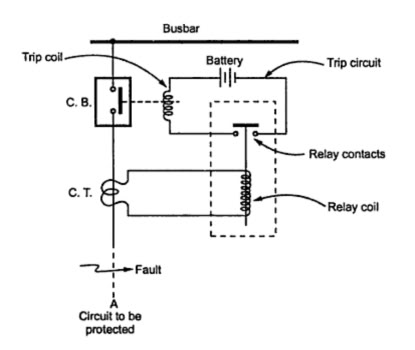
A trip unit is electrically connected in parallel with a current-limiting polymer element in series with circuit breaker contacts to function as a shunt resistance for the polymer element. It becomes energized when the polymer element transitions to its...
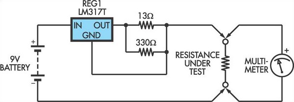
This adapter circuit functions as a 100mA constant current source. It is connected across a low-value resistor, the resistance of which is to be measured, and the resulting voltage drop can then be assessed using a digital multimeter (DMM)....
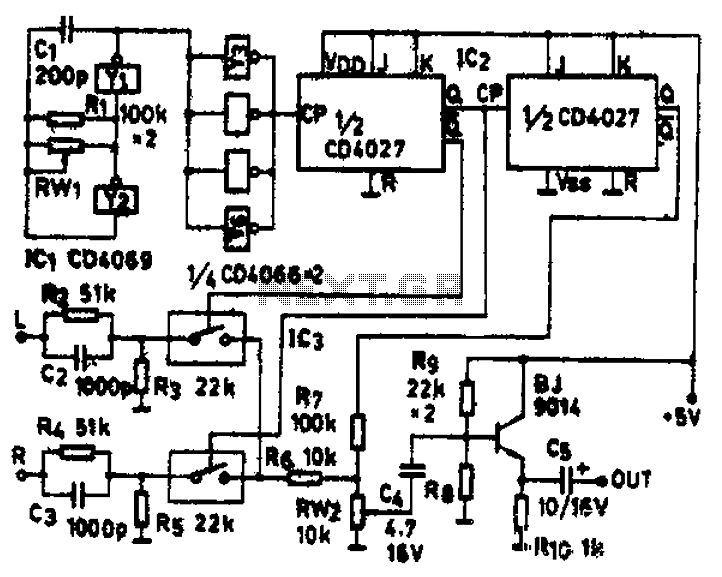
The circuit schematic diagram features IC1 (4069) and components Y1 and Y2, which together form a frequency oscillator operating at 76 kHz. Components Y3 to Y6 provide isolation and shape the output into the IC2 (CD4027) dual JK flip-flop,...
The circuit operates at a voltage of 9V with a current consumption of only 5mA. It allows for frequency adjustment within the range of 150 to 180 kHz, featuring a bandwidth of approximately 20 kHz. This configuration ensures that...
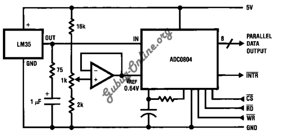
This is a design for a temperature-to-digital converter circuit that is controlled by the LM35 integrated circuit. The LM35 is a precision integrated circuit temperature sensor, whose output voltage is linearly proportional to the Celsius temperature. The circuit utilizes the...

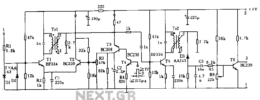
A field strength meter utilizing a biased Schottky detector employs a temperature-compensated Schottky diode within an amplified, untuned field strength indicator powered by two AA cells. This device indicates the relative field strength of RF fields ranging from a...