
A flash voice delay circuit
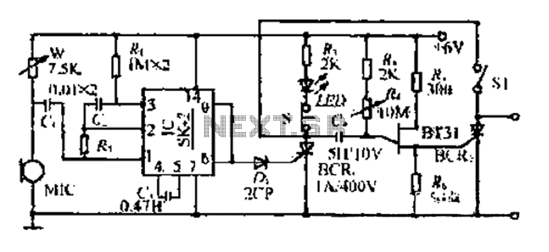
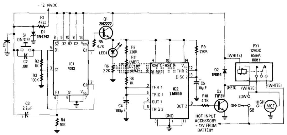
The described circuit functions as a sound-activated flash trigger for photographic applications. The microphone (MIC) detects sound waves generated by an object, converting them into an electrical audio signal. This signal is then routed through a coupling component to the integrated circuit (IC), which amplifies the signal to a sufficient level, specifically at the output pins 6 and 9 of the IC.
The amplified signal serves as a trigger for the thyristor (BCR), which is a semiconductor device that can switch on and off electrical currents. When the thyristor is activated, it allows current to flow through resistor R4, charging capacitor C4. The charging of C4 is crucial, as it determines the timing of the flash. The voltage across C4 will rise until it reaches a predetermined threshold, which is set to correspond with a specific delay after the initial sound detection.
Once the voltage across C4 exceeds this threshold, it triggers a relaxation oscillator circuit that further activates the thyristor, leading to the conduction phase. This phase causes the flash mechanism to operate, producing a brief but intense burst of light, which is essential for exposing photographic film. The exposure occurs while the system is in a wait state, allowing for the capture of images based on the sound-triggered event.
After the flash has been emitted, the circuit includes a normally closed switch (F NC) that, when released, turns off an LED indicator, signaling the end of the flash activity. The system is designed to be ready for subsequent operations, with an adjustable voltage across the microphone, ensuring optimal sensitivity and performance, set to operate within a range of 3 to 5 volts. This flexibility allows for the circuit to adapt to various sound levels and environmental conditions, making it suitable for diverse photographic scenarios.1C is SK - 2 integrated voice, when the object hit the sound is received in the body Xi ester cylinder MIC, the audio signal goes through a coupling obstacle to 1C. After ampli fication of the signal by the IC, the output of 6,9 feet provider level. After D- triggered thyristor BCR. Turned on, the capacitor C4 through R4 wide electricity. When C4 voltage reaches a certain value (ie n-inch seam after a given delay), single-junction pipe (BT31) the relaxation oscillator + Xu triggered thyristor BCR/conduction, so tr Wherever flash light, this time photographic hunger Bf] to open the IF in a wait state, so the film exposure. Delay time by the wind i ~ i Zan. When the flash is finished Wherever Mighty, press F NC press fS (light-emitting diode/ED off). R is ready to pick the next action as may be required to delay the hand F Off Sl closed sets. W compact fluorescent adjusted so that the voltage across the MIC for the 3- 5v.
Related Circuits
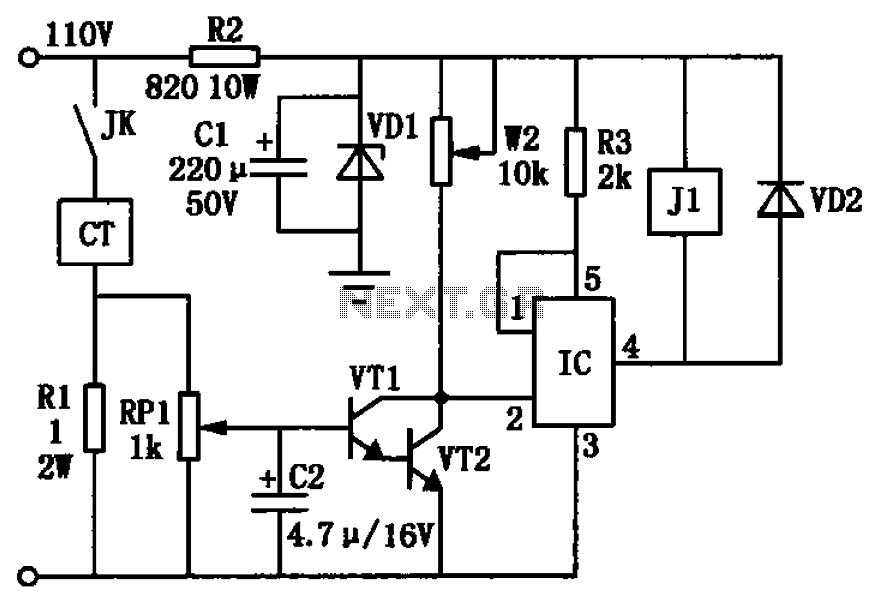
The circuit depicted in the figure utilizes a +24V power supply derived from a 110V power source through an electromagnetic chuck. When the electromagnetic chuck circuit is activated, the contact JK closes, enabling the operation of the magnetic chuck....
The most extreme option would be to supply power through a battery pack. A more plausible source would be the car's battery. However, since the objective of the circuit is to activate the buzzer when the headlights are on,...

This circuit is intended as a reliable replacement to thermally-activated switches used for Christmas tree lamp-flashing. The device formed by Q1, Q2 and related resistors triggers the SCR. Timing is provided by R1, R2 & C1. To change flashing...
This circuit utilizes a 555 timer to control a 4017 decade counter. The outputs from the counter are used to drive transistor relay drivers. The duration for which the lights remain "on" can be adjusted by modifying the connections...
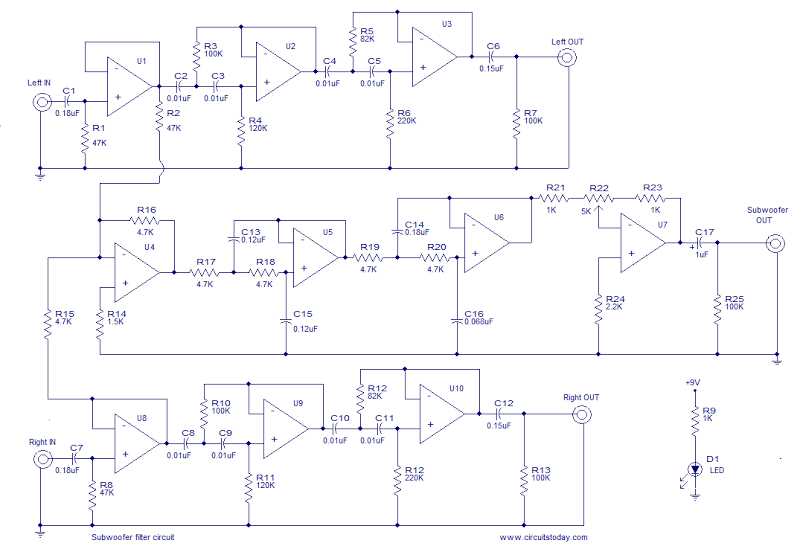
This is the schematic diagram of an operational amplifier (op-amp) based subwoofer filter. Audio frequencies below 200 Hz are typically categorized within the subwoofer range, indicating that a subwoofer filter should have a cutoff frequency around 200 Hz. The...
In the wiper-delay schematic presented, when the ignition is activated, Di maintains a regulated +12 V DC. Upon closing SI, CI bypasses transients and allows this +12 V DC to reach the resistor divider R2-R3, generating a TTL high...
Warning: include(partials/cookie-banner.php): Failed to open stream: Permission denied in /var/www/html/nextgr/view-circuit.php on line 713
Warning: include(): Failed opening 'partials/cookie-banner.php' for inclusion (include_path='.:/usr/share/php') in /var/www/html/nextgr/view-circuit.php on line 713