
Headlight Alarm Circuit
The circuit is designed to operate primarily with low power consumption while ensuring reliable buzzer activation under specified conditions. The PNP transistor serves as a key component for controlling the buzzer based on the state of the accessory line and the headlight circuit. The accessory line, when in an active state, provides a base current to the transistor, allowing it to turn on and connect the collector to the emitter, thus powering the buzzer. The resistor placed in series with the accessory line ensures that the base current does not exceed the maximum rating of the transistor, protecting it from damage.
This circuit can be particularly useful in automotive applications where alerting the driver about the status of the headlights is crucial for safety. The design is straightforward, utilizing commonly available components, which facilitates easy assembly and troubleshooting. The choice of using a PNP transistor allows for efficient operation within the automotive voltage range, which typically spans from 12V to 14.5V in running conditions. Furthermore, the inclusion of a protective resistor ensures that the circuit remains within safe operating parameters, enhancing the longevity of the components involved.
For prototyping, attention should be paid to the layout of the circuit to minimize noise and ensure stable operation. Proper grounding practices should be observed, particularly when dealing with automotive environments where electromagnetic interference can be prevalent. The final assembly should include an enclosure that protects the circuit from environmental factors and mechanical stress, ensuring reliable operation over time.The most outrageous option would be to provide power via a battery pack. A more likely source would be the car`s battery. However, since the circuit`s goal is to sound the buzzer when the headlights are on, we might as well take the power from the headlights. In order to sound the buzzer when the car is off, there are two things to consider. First, a signal source needs to be determined. In the case of my circuit, I chose an accessory line. The accessory line is be grounded when the power is cut (car off) and is otherwise on, so we`ll have an easy comparison. Second is the problem of determining when the accessory line is low. I first considered a comparator, but I soon realized that all I would need is a PNP transistor to switch the buzzer on and off.
With this component, the headlight line is connected to the emitter, the base is connected to the accessory line, and the collector is connected the buzzer. Therefore, when the headlights are on and the accessories are off, the emitter conducts to the collector and the buzzer sounds.
Also with this arrangement, if the headlights are off or the accessories and headlights are on, nothing happens. Additionally a resistor is connected between the accessory line and the transistor to limit the current flowing to ground when the buzzer is sounding.
As you can see in the diagram, the headlights are on and the accessories are off. There is a little less than battery voltage flowing through the buzzer and ~1mA leaking to ground through the transistor. The transistor in the design was chosen specifically since it was rated for much higher voltage than what the circuit will ever see.
It should be possible to use a general purpose transistor, but I did not want to bother with it. After proving the circuit design in Multisim, I moved on to prototyping. This circuit can be built, complete with enclosure, from the following Mouser components (1 each): 🔗 External reference
Related Circuits
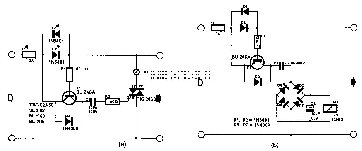
The circuit in Fig. 56-lla activates a signal lamp when it detects a line current consumption exceeding 5 mA and can handle currents of several amperes using suitable diodes in the D1 and D2 positions. Transistor T1 is activated...
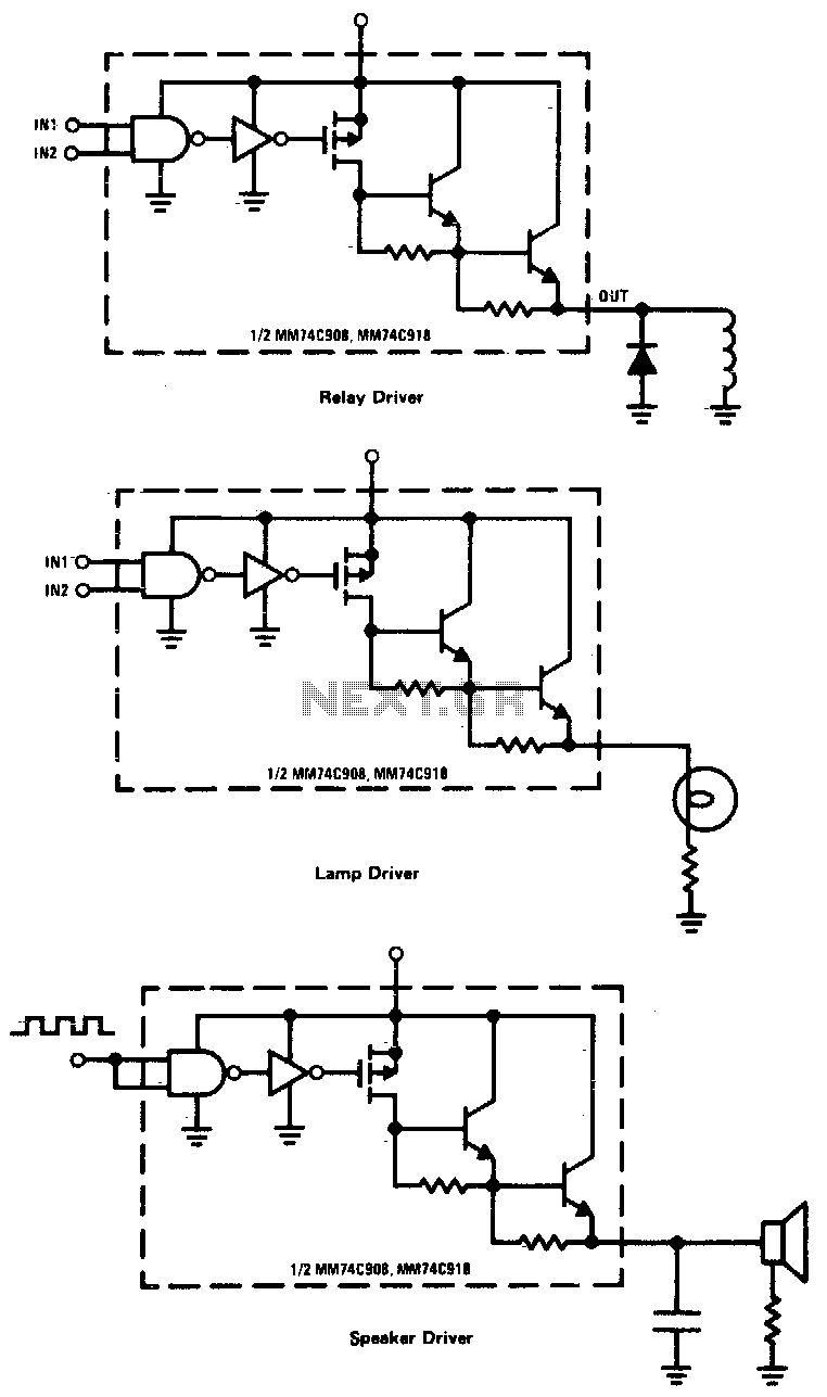
CMOS drivers for relays, lamps, speakers, and similar applications provide extremely low standby power consumption. When operating at Vcc = 15 V, the power dissipation per package is typically 750 nW when the outputs are not drawing current. Consequently,...
The circuit operates on the principle of detecting smoke produced during a fire, which passes between a light bulb and a light-dependent resistor (LDR). As smoke obscures the light, the amount of light reaching the LDR decreases, resulting in...

Maxim has introduced a series of five integrated oscillator building blocks in the MAX260x series, covering a frequency range of 45 to 650 MHz. The MAX2606 is designed for the VHF band, allowing frequency variation of approximately ±3 MHz...
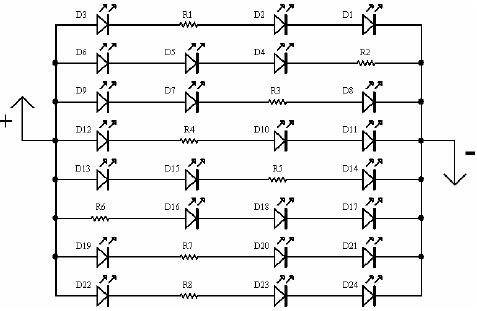
A light-emitting diode (LED) lamp is a solid-state lighting device that utilizes light-emitting diodes as its light source. LEDs are a cost-effective and convenient choice for various lighting applications. They are available in an extensive range of colors, styles,...
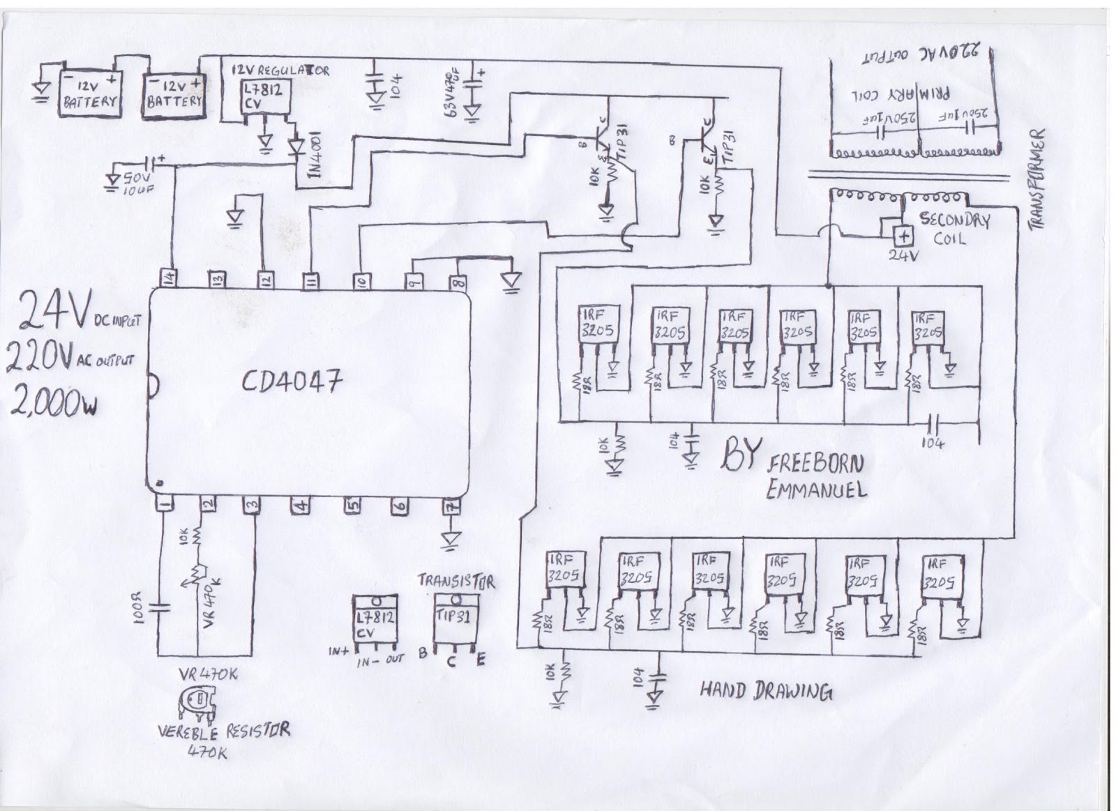
The diagram illustrates a modified square wave inverter circuit. By adjusting the frequency resistor (VR 470k), the inverter's output frequency can be optimized to effectively power a freezer compressor and various other electronic appliances in a living room. The...
Warning: include(partials/cookie-banner.php): Failed to open stream: Permission denied in /var/www/html/nextgr/view-circuit.php on line 713
Warning: include(): Failed opening 'partials/cookie-banner.php' for inclusion (include_path='.:/usr/share/php') in /var/www/html/nextgr/view-circuit.php on line 713