
A hydraulic circuit diagram showing

The circuit operates on the principle of using an oil pressure sensor that functions as a variable resistor, Rt. As the oil pressure in the system changes, the resistance value of Rt also changes correspondingly. This variation in resistance influences the biasing conditions of three transistors arranged in a configuration that allows them to control the current flowing to three different LEDs, each representing a specific pressure range.
The transistors are configured such that they are biased differently based on the resistance value of Rt. When the oil pressure is low, Rt increases, causing the first transistor to turn on, which in turn activates the red LED, signaling low pressure. As the pressure increases and Rt decreases, the biasing condition shifts, leading to the activation of the yellow LED at an intermediate pressure level. Finally, when the pressure reaches a certain threshold, the green LED is illuminated, indicating a safe operating pressure.
The selection of the bias resistor is critical in this design. It must be chosen to ensure that the transistors switch on and off at the correct thresholds corresponding to the desired pressure levels. This ensures that only one LED lights up at any given time, providing a clear and unambiguous indication of the hydraulic pressure status. The circuit provides a simple yet effective visual representation of pressure levels, enhancing the monitoring capabilities in hydraulic systems.FIG circuit, the oil pressure sensor is converted into a variable resistor Rt. Due to changes in Rt, changing the size of each transistor is biased, three LEDs (red, yellow, gr een) under forward bias in a different light. Therefore, as long as the bias resistor is appropriately selected, it can ensure that only one light emitting diode, to indicate the corresponding hydraulic pressure.
Related Circuits
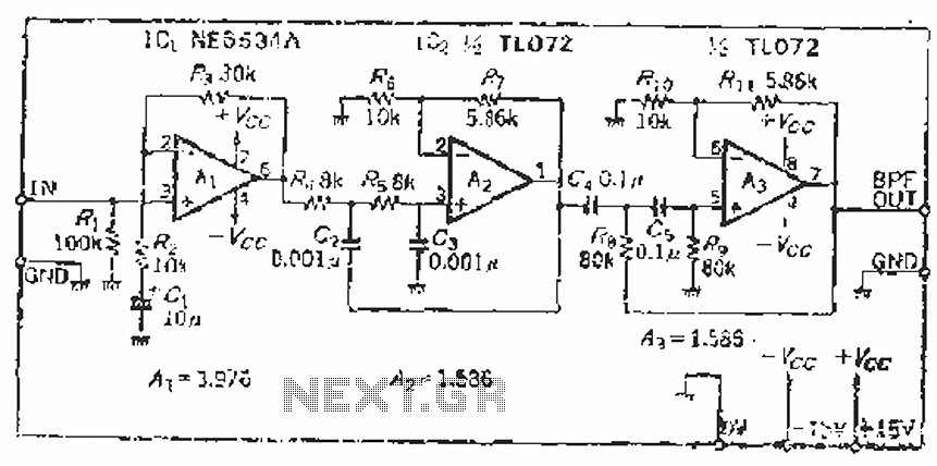
The filter incorporates a zoom function, with a front satin amplifier magnification calculated as d = 10/2.515 = 3.97, which results in a total beam compared to a 10 times magnification. The low-pass filter parameters are specified as a...
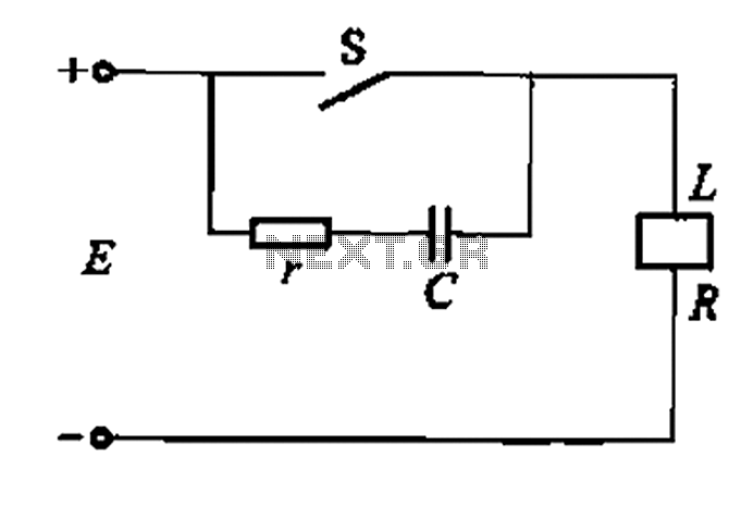
A resistor-capacitor circuit designed to prevent spark blowout. The coil's magnetic energy is converted into electrical energy stored in the capacitance C, effectively suppressing sparks and enhancing safety. The circuit is capable of functioning normally even with reverse polarity....
This sound level measuring device circuit can be used to control the intensity of a sound recording in the field of a disco. It has five measurement ranges between 70 and 120 dB, with a measurement accuracy of 0.5...
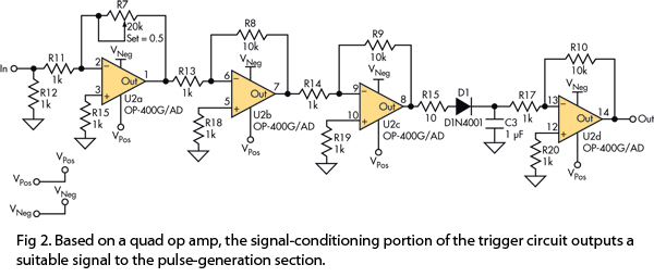
This version of the trigger circuit for the stop-motion camera system utilizes an electret microphone for sonic input, although it can be replaced with an LED and photodiode pair for optical triggering. A recent home-built project involved constructing a...
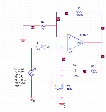
In this laboratory experiment, the objective is to design the frequency-determining network for a 1 kHz sinusoidal oscillator. The specified values are as follows: Capacitance = 100 nF and Resistance = 1520 ohms. The output voltage waveform of the...
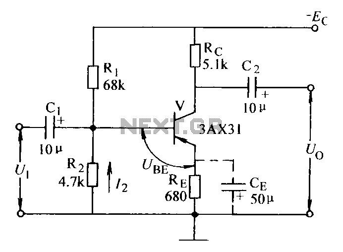
Current negative feedback voltage divider biased circuit diagram. The current negative feedback voltage divider biased circuit is a configuration commonly used in electronic amplifiers to stabilize the operating point and improve linearity. This circuit typically consists of an amplifier, a...