
Measuring SN audio bandpass filter circuit
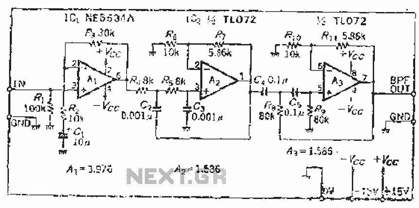
The described circuit features a combination of low-pass and high-pass filters, which are critical in audio and signal processing applications. The low-pass filter is designed to allow signals below a certain frequency (20 kHz) to pass while attenuating higher frequencies. The quality factor (Q) of 0.707 indicates a standard Butterworth filter configuration, which provides a maximally flat frequency response in the passband. The capacitance value of 0.001 µF (1 nF) is essential for determining the filter's cutoff frequency in conjunction with the resistance values calculated.
The resistance value Rs = 7.96 kΩ plays a significant role in establishing the filter's impedance and affects the overall gain of the circuit. The inductance value of L = 10 kΩ (A-1) = 5.86 kΩ suggests that there may be an additional element or configuration influencing the filter's behavior, possibly indicating a series or parallel arrangement with other components.
On the other hand, the high-pass filter is designed to allow signals above 20 Hz to pass while attenuating lower frequencies. The Q factor remains at 0.707, ensuring a smooth transition at the cutoff frequency. The capacitance of 0.1 µF is larger than that of the low-pass filter, which results in a different response characteristic. The resulting resistance values of Rs = Rt = 79.8 kΩ indicate a high impedance path, which can be beneficial in applications requiring minimal loading on the source signal.
Overall, the combination of these filters allows for precise control over the frequency response of the system, making it suitable for various applications in audio processing, communications, and signal conditioning. The design considerations of both filters ensure that the circuit can effectively manage the desired frequency components while suppressing unwanted noise and interference.Since the filter has a zoom function, front satin amplifier magnification such as d = 10/2. 515 = 3,97, the beam of the total, compared with 10 times magnification. Low-pass filter parameters, according to] r five = 20k Hz, Q = 0.707, mouth if taken 0. ooiuF, you can find Gong = Rs = 7.96kQ, Lu T = iokfl (A-1) = 5.86kQ. High-pass filter parameters, ugly - 20Hz, Q = 0. 707, if cd = c5 = 0.1 liF, you can find Rs = Rt = 79, fikQO
Related Circuits
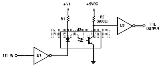
This circuit is a TTL-to-TTL isolator circuit. The driver circuit is an open-collector TTL inverter (U1). When the input is high, the output of the inverter is low. Thus, when the input is high, the output of U1 grounds...
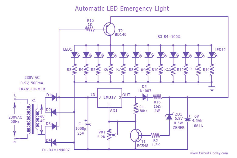
This is a cost-effective and straightforward emergency light circuit developed for CircuitsToday. It is an automatic emergency lamp with daylight sensing capabilities, meaning it detects darkness and turns on automatically, while also sensing daylight to turn off. The circuit...
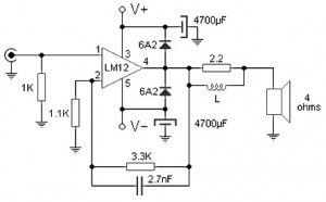
The 100W audio power amplifier is powered by the integrated circuit LM12CLK, which is an operational power amplifier. The 100W audio power amplifier utilizing the LM12CLK integrated circuit is designed to deliver high-quality audio output with significant power handling capabilities....
This device is a highly effective capacitive sensor. In North America, it is primarily utilized for detecting wooden beams behind drywall or plaster. This model is preferred over newer designs due to its reliability, as it does not frequently...
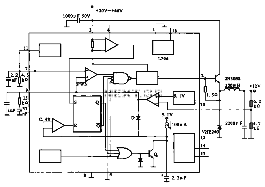
The circuit outputs 12V at 10A and utilizes a high-current switching power supply design based on the L296 component. This configuration allows for an output current of up to 10A, and the entire circuit is compact with minimal component...
This is a car alarm simulator that uses an LED as a simulation output. This simple circuit can indicate whether a car is running or not by detecting the voltage difference when the car is on or off. This...
Warning: include(partials/cookie-banner.php): Failed to open stream: Permission denied in /var/www/html/nextgr/view-circuit.php on line 713
Warning: include(): Failed opening 'partials/cookie-banner.php' for inclusion (include_path='.:/usr/share/php') in /var/www/html/nextgr/view-circuit.php on line 713