
sound level meter circuit
The sound level measuring device circuit is designed to provide an accurate and reliable measurement of sound intensity, particularly in environments such as discotheques where sound levels can vary significantly. The circuit operates within a specified range of 70 to 120 dB, making it suitable for various applications in sound engineering and audio production.
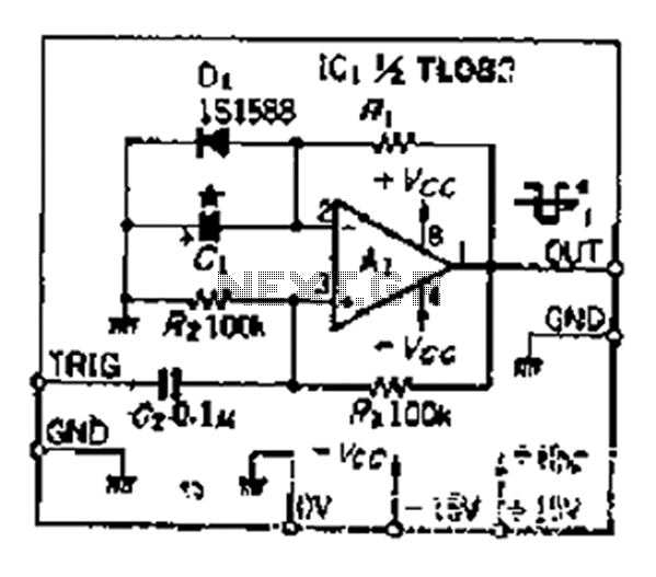
The heart of the circuit is the operational amplifier IC1, which is configured to amplify the signal received from the microphone. The microphone M1 captures sound waves and converts them into an electrical signal. This signal is then conditioned by the input filter formed by capacitors C1 and C2 and resistors R1 and R2, which eliminate unwanted noise and ensure that only the desired frequency components are passed to the amplifier.
The sensitivity of the operational amplifier can be adjusted using switch S2, which allows the user to select one of the five measurement ranges. This feature is particularly useful for adapting the instrument to different sound environments and ensuring accurate readings across a wide range of sound levels.
The output from IC1 is an alternating voltage that is rectified by diodes D1 to D4. The rectification process transforms the AC voltage into a DC voltage that can be easily read by the indicator tool. Resistor R9 is used to limit the current flowing to the indicator, ensuring that it operates within safe limits.
To protect the circuit from excessive voltage levels, diode D5 is included. This diode acts as a clamping device, preventing the output voltage from exceeding a certain threshold, which could otherwise damage the indicator or other circuit components.
Powering the circuit with two 9V batteries provides sufficient current for operation, with a typical input current of around 2 mA. This low power consumption allows for extended use in the field without frequent battery replacements. The inclusion of switch S1 enables the user to disconnect the circuit when not in use, further conserving battery life.
Overall, this sound level measuring device circuit is a practical tool for monitoring sound levels in various environments, providing users with the ability to ensure sound intensity is within acceptable limits for both safety and quality purposes.This sound level measuring device circuit can live used to control the intensity of a sound recording before in the field of a disco. It has 5 measurement domains connecting 70 and 120 dB; recital accuracy is 0. 5 dB. Microphone M1 is used to receive the acoustic imply and is coupled to C1, C2, R1 and R2. This components, composed with the micropho ne`s office and with the input impedance of the amplifier form an input filter. The filtered hint at goes to operational amplifier IC1 whose sensitivity can subsist switched with S2 corresponding to the five measuring domains. D1 D4 diodes rectifies the alternating voltage next to the amplifier output and feeds the indicator tool through R9.
D5 is used indoors order to watch over the sound level gauge indicator opposed to soaring voltages; it limits the rectifier`s output voltage after the sound level is too high. On standard conditions the input current is just about 2 mA to is why the circuit can live powered with 2 x 9V batteries.
S1 switch is used to disconnect the sound level gauge device afterward measurement. The indicator tool ought to tolerate a graded amount in the field of dB with the greatest extent profit of +10. 🔗 External reference
Related Circuits
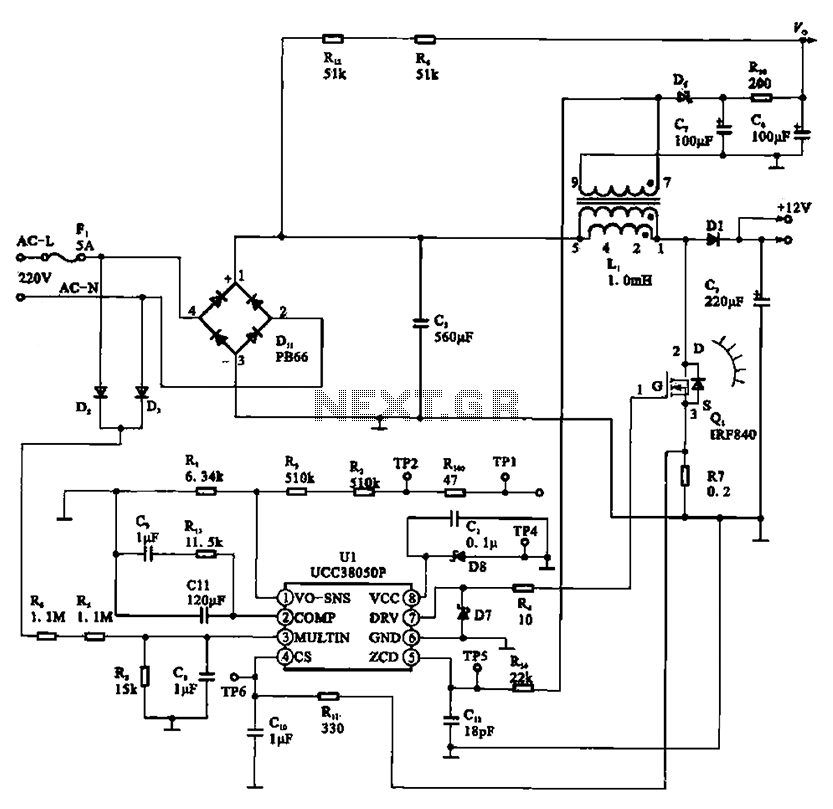
A typical laptop power adapter circuit converts an AC input of 22V through a rectifier and filter circuit to produce an output of +30V DC. This voltage is then processed by a switch oscillation circuit (U1, UCC38050P), which controls...
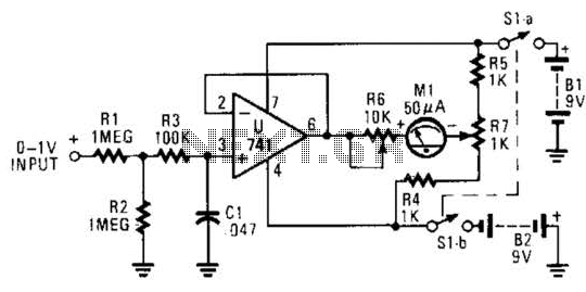
The circuit is designed around a 741 general-purpose operational amplifier (op amp) configured as a voltage follower, providing a voltage gain of one. The output from the 741 is utilized to drive a 50-meter movement. Potentiometer R7 is employed...
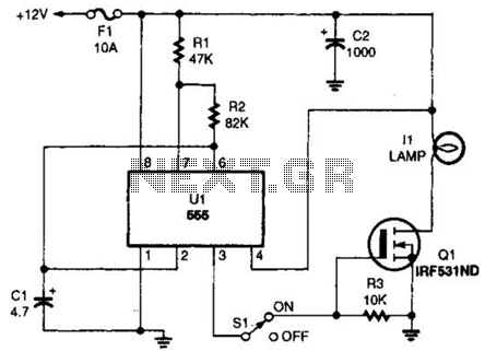
The headlight flasher is a 555 oscillator/timer configured as an astable multivibrator (oscillator). Its input is used to drive the gate of an IRF53IND hexFET, which acts as an on/off switch, turning the lamp on and off at an...
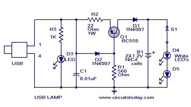
A simple USB LED lamp circuit utilizing a 5-volt power supply sourced from a USB port, designed to illuminate a desktop or laptop computer during power outages. The USB LED lamp circuit operates by converting the 5-volt DC power provided...
Camping today often involves various electronic accessories for daily activities or entertainment. Typically, a portable battery charger and a power inverter are used to ensure a well-organized campsite where both adults and children can comfortably use their electronic devices....
Although people believe that using a timer with an operational amplifier (op-amp) does not yield significant results, it can still be advantageous in certain scenarios. In environments with high noise levels, the application retains its benefits. When the phase...