
A Journey into Building Radio Transmitters with Vacuum Tubes
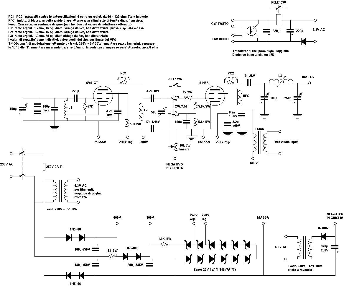
The circuit design for the one-tube short-wave transmitter employs a Sovtek 6L6 WXT+ tetrode configured as a Hartley oscillator. This circuit utilizes a combination of inductive and capacitive elements to generate RF signals. The main components include the tetrode, a hand-wound RF choke designed in a honeycomb configuration to reduce stray capacitance, and a pi network comprising variable capacitors for tuning.
The RF choke plays a crucial role in the plate circuit, allowing for stable oscillation while preventing unwanted feedback into the grid circuit. The tuning of the grid and plate networks is essential for achieving the desired frequency output. Initially set for the 20-meter band, the tuning was adjusted to the 40-meter band to resolve oscillation issues caused by coupling between the two networks.
The circuit layout should ensure proper spacing and orientation of the coils to minimize interference. The use of recycled enclosures from computer power supply units not only provides a compact form factor but also emphasizes sustainability in electronic design. The output stage is capable of delivering over 50 watts of RF power, making it suitable for short-wave transmission.
Safety considerations are paramount, particularly due to the high voltages involved. The circuit rectifies and doubles the mains voltage to achieve the necessary plate and screen voltages, resulting in a chassis potential of -300 V relative to ground. This necessitates careful handling and isolation to prevent electrical hazards. Overall, this one-tube short-wave transmitter exemplifies a blend of vintage technology and modern DIY ingenuity, illustrating the enduring appeal of vacuum tube circuitry in amateur radio applications.A copy from an old italian magazine of amatorial electronics, proposing an add-on for tube receivers. The add-on was a simple one-tube short-wave transmitter leveraging the same power supply already available in the receiver.
This circuit fascinated me when I was just a teenager. I was quite a nerd when I was a teenager. Sure, besides being very c lever at school, I was into any sort of strange hobbies including electronics. My father was seemingly proud of this. Perhaps my mother was a bit concerned, instead. You know, a male teenager is rather expected to hang out with friends, seek a girlfriend, etc. The project reported in that old magazine fascinated me at that time, because I had a tube receiver at home, and I got a spare tube from another old receiver so I apparently had almost all the ingredients. The only missing piece was the plate RF choke, but I managed to build what at that time I presumed to be a good approximation of it.
So I tried! But I was unsuccessful. The reason of that early insuccess was a fundamental lack of specific knowledge in RF electronics. I had no actual chance to spread RF in the air, despite the schematics and the components, because for instance I knew nothing about antennas, transmission lines, and impedance matching. I will always be grateful to the poor victim of these early and cruel experiments, namely, a 6V6 tube that has survived nevertheless.
Vacuum tubes are generous and patient, they tolerate our mistakes, and this is the main reason why I keep loving them for my RF experiments, despite the dangerously high voltages required for operation. First serious attempt: one-tube tx using a Sovtek 6L6 WXT+ tetrode in a Hartley electron-coupled oscillator.
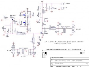
Circuit schematics is missing, but it was very similar to the one I attempted to build when I was a teenager. As apparent in the picture, the rig was enclosed in a plastic container originally intended for storing food into the fridge.
The plate circuit of this rig requires a RF choke (see the approximate schematics ) which is usually wound according to the famous "honeycomb" fashion to minimize stray capacitance. Since I was unable to find one in any shop, I had to roll my own one. It was fun to envisage a procedure for building it, and a nice bricolage when doing! You can look at the result in the next section. Originally, both the grid and the plate networks were tuned in the 20 mt band; this way, however, the rig was almost impossible to tune.
It looked like the plate network was oscillating on its own, taking over the grid resonant circuit (sort of "tuned-not-tuned" rig). This was perhaps caused by some coupling between the grid resonant network and the plate network, although the respective coils were mounted orthogonal to each other.
As a remedy, the grid was then tuned in the 40 mt band while leaving the plate pi network on the 20 mt (frequency doubler). The picture shows the two vacuum tubes (6146B on the left, 6V6 GT on the right), and the two separate enclosures (one for the rig and the other for the power supply unit); both are recycled from computer`s broken power supply units.
Another picture shows the unusually tiny size of this rig, in comparison to a mobile phone. A look at the interior shows the hand-wound honeycomb RF choke (enameled copper, hence the colour) already mentioned in the previous section. Finally, a picture of the final pi network shows the usual coil and the two variable capacitors. Output RF power is in excess of 50 watt. In the early version of the rig, the VFO was a Hartley oscillator (see early schematics ), later replaced by a Clapp oscillator; look at the schematics for details.
Note that the plate and screen voltages are obtained by rectifying and doubling the mains, without any transformer. As a result, the chassis is at a dangerous -300 V with respect to ground. A galvanic connection to ground is thus impossible, unless a isolation trasfor 🔗 External reference
Related Circuits
This FM 88-108 MHz radio amplifier is equipped with a BLF 245 and can be used with a heatsink from a processor and a cooler. The BLF 245 datasheet can be downloaded. The FM 88-108 MHz radio amplifier utilizing the...
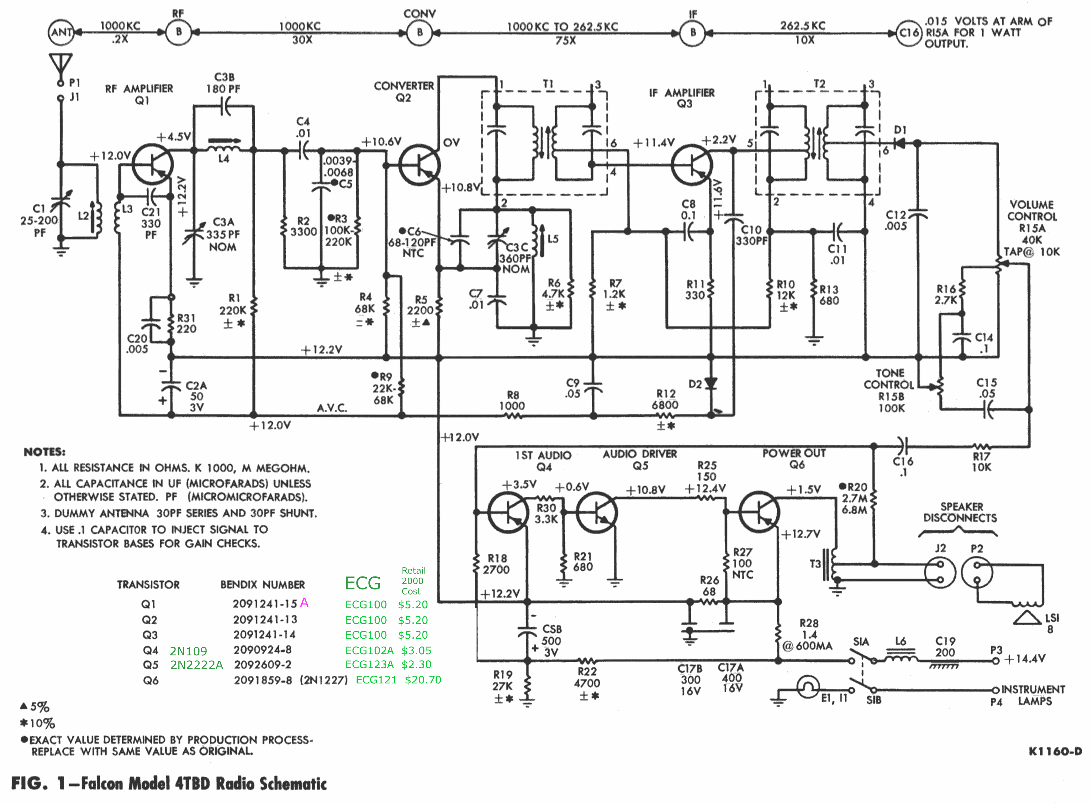
The chassis externally resembles the 22BD model, with the exception that the 22BD features a jack for speaker connections—two female sockets—located on the right (antenna) side. In contrast, the 3BTD model has a 3-inch harness (black and green wires)...
A simple radio receiver circuit is illustrated. This receiver is designed to capture signals from amateur radio stations operating in the shortwave (SW) bands of 10, 15, 20, 40, and 80 meters. The direct-conversion receiver comprises a set of...
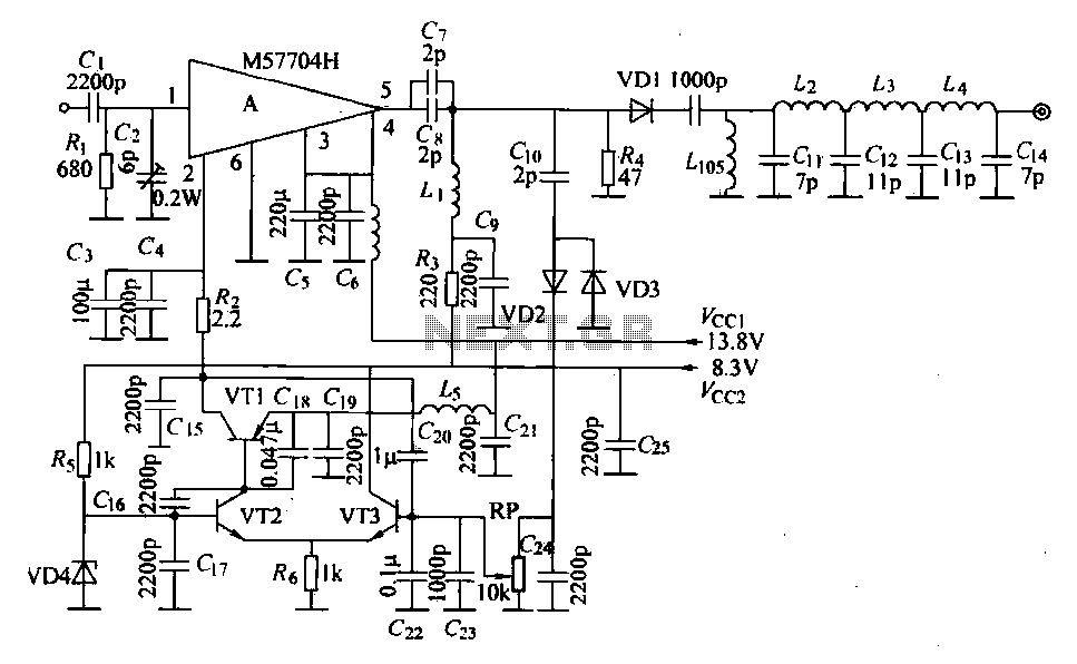
The FM radio transmitter is a high-frequency amplifier circuit that utilizes the Mitsubishi frequency set, specifically the M57704H discharge path. It operates within the frequency range of 457-458 MHz and has a transmission power of 5 watts. As illustrated...
This document describes an earlier version of a project that has been found to be quite unreliable. The project is ongoing, with periodic updates being posted until a proper design and rig are developed, at which point a new...

The CMX866 is a multi-standard modem designed for use in telephone-based information and telemetry systems. Control of the device is achieved through AT commands via a simple 9600 b/s serial interface, which is compatible with various types of host...
Warning: include(partials/cookie-banner.php): Failed to open stream: Permission denied in /var/www/html/nextgr/view-circuit.php on line 713
Warning: include(): Failed opening 'partials/cookie-banner.php' for inclusion (include_path='.:/usr/share/php') in /var/www/html/nextgr/view-circuit.php on line 713