
Repair Notes for Bendix Model 3TBD AM Radio
The 3BTD model's design incorporates a unique harness configuration that distinguishes it from the 22BD model, impacting the connectivity and integration with external components. The arrangement of the connectors and the layout of the transistors within the amplifier stage are critical for the radio's performance. The RF, converter, and IF stages must be thoroughly tested to ensure that they are operational, as failure in any of these stages will prevent proper signal reception. The use of an oscilloscope during the tuning process is vital, as it allows for real-time monitoring of the signal waveform, ensuring the radio is aligned with the intended frequency.
When diagnosing issues within the amplifier stage, a systematic approach should be taken. If the collector voltage of a transistor is found to be near zero, it is essential to replace that component, as it indicates that the transistor is likely open and not functioning as intended. In many cases, the rapid identification of faulty transistors can significantly reduce repair time, allowing for efficient restoration of service.
Furthermore, the decision to replace all transistors on the mainboard as a preventive measure is a prudent strategy, especially considering the age of the components and the potential for future failures. The choice of replacement parts should take into account not only compatibility but also the performance characteristics necessary for reliable operation in the specific application.
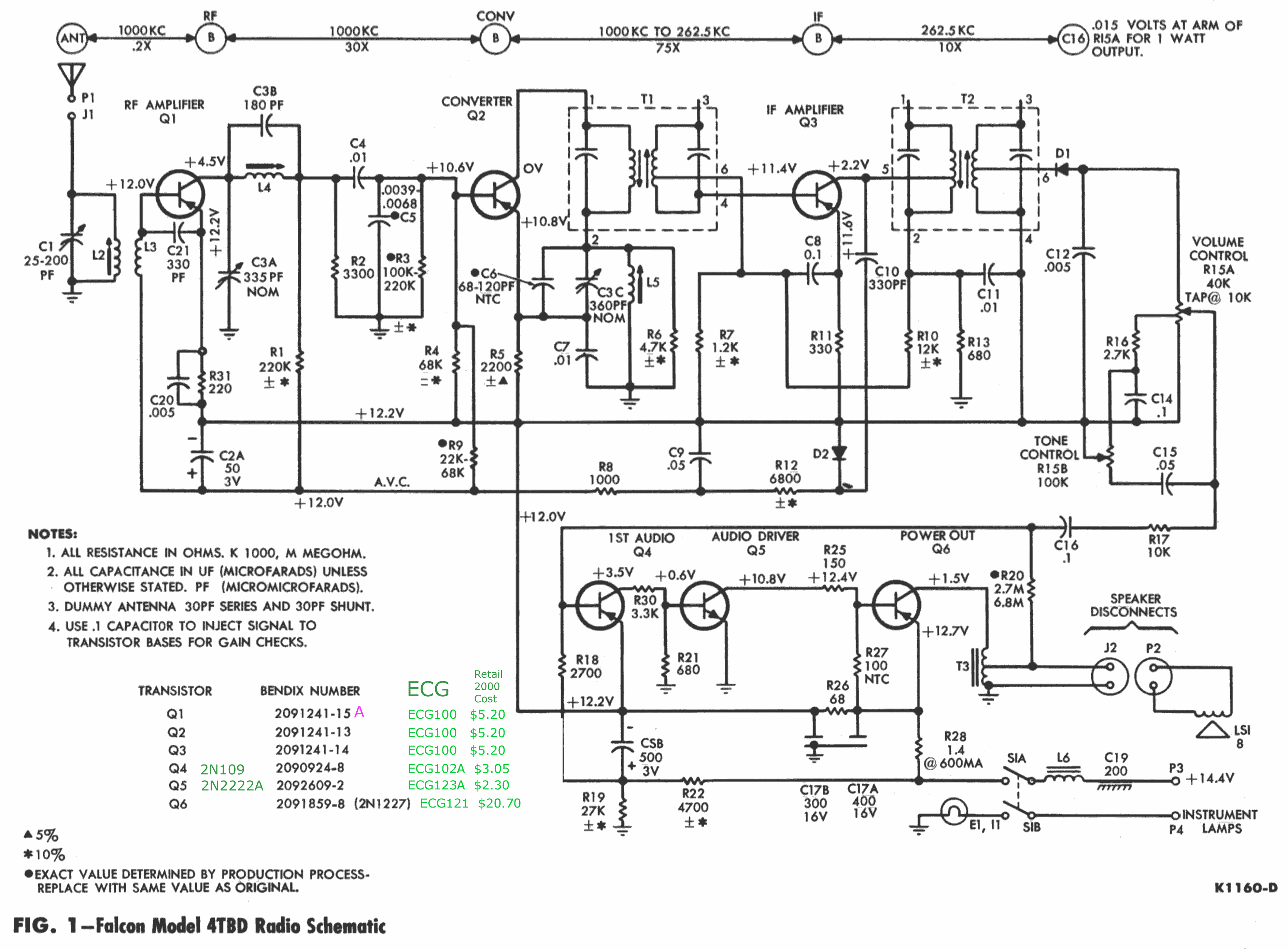
In conclusion, the maintenance and repair of early solid-state radios, such as the 3BTD model, require a comprehensive understanding of the circuit design, component behavior, and diagnostic techniques. By adhering to best practices in component replacement and utilizing appropriate testing equipment, the longevity and functionality of these vintage devices can be preserved.Externally, the chassis looks identical to the 22BD. Exception: the 22BD has the jack for the speaker connection - two female sockets - on the right (antenna) side of the chassis; the 3BTD has a 3" harness (Black and Green wires) exiting the left side (same side as the power leads) and is a combined male/female connector. Refer to the pics I have of the earlier 22BT model. A good location to find the AM signal, is the connection shown below (if the RF/Converter/IF stages are OK). You`ll only get a waveform if you`ve tuned in a station, so watch the `scope while tuning. . . I pulled the first two transistors in the amplifier stage (Q4 & Q5) and they looked good and checked OK, checked a few resistor values, all looked OK, soldered everything `em back in and lo!
All of a sudden, it plays. I *hate* that. "Early solid state car radios used all germanium transistors. The most common failures were the RF amp, Local oscillator, and the converter (Mixer) transistors. The easiest way to find the bad transistor is to check the collector votages. If you find one that`s near zero, the transistor is open. I used to test, find the bad part and repair the radio in less time than the service clerk took to write up the work order, and all I used was a meter, signal tracer, and an old signal generator. Over 95% of the failures were open transistors, and the replacement parts weren`t critical Something rated for RF in the low ECG numbers worked very well.
" Well, open transistors are not terribly common on the monitors I`ve repaired (different tech, different era, no germanium stuff), so I am grateful for this advice from someone who`s been there. After two days` running on the bench, the radio is still running fine, but I think I`ll just replace all the transistors on the mainboard (Q1 through Q4), because I don`t want to pull this again for a while, and they`re probably cheap.
Q4 (NTE/ECG102A, 2N109) is almost certainly where the problem was. Q5 is a silicon part, not germanium, so I didn`t replace it. Its modern equivalent is a 2N2222, which is not an especially trouble-prone part unless overloaded, and certainly doesn`t go intermittent. I was unable to use the NTE100 to replace Q2; the old Q2 works OK, but subbing the NTE100 yields no output.
This must be one of those circuits in which the NTE "equivalent" isn`t. 🔗 External reference
Related Circuits
PARTS LIST C1 0.22 µF (224) C2 22nF (223) C3 10nF (103) C4 27pF C5 22pF C6 3.3nF (332) C7 180pF (181) C8 330pF (331) C9 3.3nF (332) C10 150pF (151) C11 82pF C12 68pF C13 220pF (221) C14...
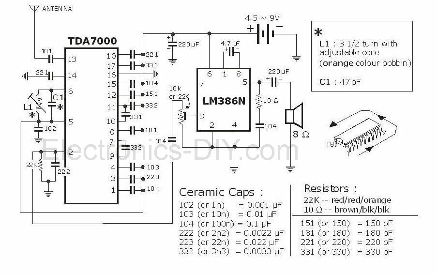
This project is an FM radio utilizing the TDA7000 and LM386 integrated circuits. The TDA7000 IC is notable for its operation as a complete FM superheterodyne receiver, incorporating the standard components such as a local oscillator, mixer, intermediate frequency...

The relay power in the linear circuit is derived from a -120 V bias supply, while the transmit keying output from the Kenwood device is +12 V with a maximum current of 10 mA. A critical component of this...
The PMR VHF transceiver Motorola Radius M110 (in further text referred as M110) was manufactured by Motorola GmbH therefore being an European radio. Since many professional radio service users has replaced this transceiver with newer gear, a considerable number...
This circuit illustrates a remote control system utilizing a radio telephone circuit diagram. Features include the ability to switch appliances from any distance, overcoming various limitations. The remote control circuit employs radio frequency (RF) technology to facilitate wireless communication between...
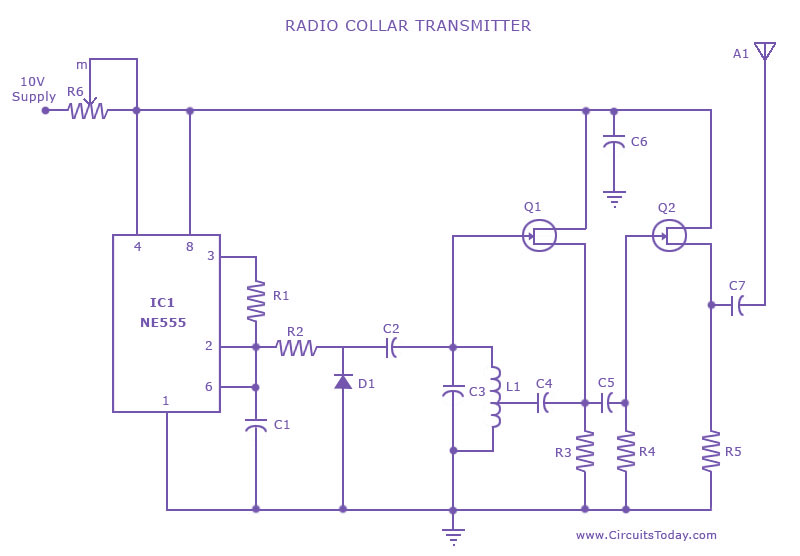
This is a radio transmitter circuit diagram designed for integration into radio collars using the NE 555 integrated circuit. The circuit transmits a pulse in the FM band, specifically between 88 MHz and 105 MHz. The radio transmitter circuit utilizes...