
HAM RADIO SW RECEIVER
The described radio receiver circuit operates as a direct-conversion receiver, allowing for efficient signal processing from amateur radio bands. The input bandpass filters are critical for isolating the desired frequency range, enhancing the receiver's ability to select specific amateur radio signals while rejecting out-of-band interference. The RF amplifier (VT1) boosts the incoming radio frequency signal, providing sufficient gain to ensure effective mixing in the diode mixer (VD1, VD2).
The mixer is pivotal in converting the RF signal to an intermediate frequency (IF), which is then processed by the audio frequency amplifier (VT3-VT5). This amplifier stage is designed for high gain to ensure that the audio signal is adequately amplified for headphone output (BF1), facilitating clear audio reception of the selected amateur radio transmissions.
The local oscillator (VT2) plays a crucial role in the frequency conversion process, generating a signal that is half the frequency of the incoming RF signal. This is achieved through the tuning capability provided by the variable capacitor (C27), allowing the user to adjust the local oscillator frequency to match the desired reception frequency.
The inclusion of the switch (SA1) for band selection simplifies the operation of the receiver, enabling users to easily switch between different amateur bands without complex adjustments.
The voltage regulator circuit, utilizing the Zener diode (VD3), ensures stable operation of the local oscillator by providing a consistent voltage supply, thereby reducing frequency drift that could occur due to variations in the supply voltage. This stability is essential for maintaining reliable reception across the various amateur bands.
Overall, the described circuit is a straightforward yet effective design for a radio receiver, making it suitable for amateur radio enthusiasts seeking to operate within the specified shortwave bands.A simple radio receiver circuit is shown in Fig. 1. This receiver is designed for reception of signals of amateur radio stations operating in the SW band of 10, 15, 20, 40 and 80 meters. This direct-conversion receiver consists of a set of an input bandpass filters tuned to the middle frequency of the amateur bands, a broadband RF amplifier based
on a transistor VT1, a diode mixer (VD1, VD2), a local oscillator (VT2) and a three-stage amplifier of audio frequency with high gain based on a transistors VT3-VT5. This amplifier is loaded with a headphones BF1. A switch SA1 is intended to switch between bands, it connects the filters to the input of the RF amplifier, and the mixer - to a corresponding resonant tank of the local oscillator.
The local oscillator is tunable by a variable capacitor C27 and it generates an oscillations with a frequency twice lower than the frequency of received signals. A simple voltage regulator is based on the Zener diode VD3 and it is used to reduce a dependence of the local oscillator frequency of a supply voltage variation.
🔗 External reference
Related Circuits
40-meter Direct Conversion Receiver. Using the circuit of a 40-meter band direct-conversion receiver described here, one can listen to amateur radio QSO signals in both CW and SSB modes. The 40-meter direct conversion receiver is designed to facilitate the reception...
This small receiver with reduced range (weight 9g, dimensions 32 x 25 mm) is suitable for slow-flyer, little boats, etc. The described receiver is designed for applications requiring lightweight and compact components, making it ideal for slow-flying aircraft and small...
A crystal radio utilizing a 1N34A germanium diode. It is recommended to use a 24-inch piece of wire for the antenna. The crystal radio circuit described utilizes a 1N34A germanium diode, which serves as a detector for radio signals. The...
This is a description of an experimental AM receiver for VLF. It is crystal controlled to receive 181.818 kHz (more or less) and operates as either a single conversion superhetrodyne or a direct conversion receiver. The bandwidths are expected...
The diagrams below illustrate the development of a simple modular radio receiver based entirely on circuits and devices studied during the Part IA course on Linear Circuits and Devices. This receiver may not revolutionize the market; however, it aims...
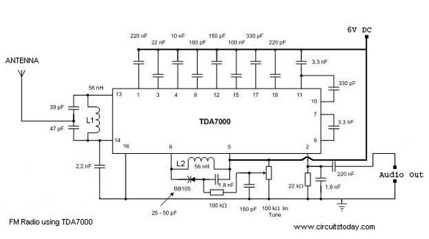
A simple FM radio circuit with a diagram and schematic using the IC TDA 7000. This low-cost single-chip FM radio circuit design is easy to assemble and is suitable for creating a portable FM radio. The FM radio circuit utilizing...