
A Light Operated Repeating Timer Circuit
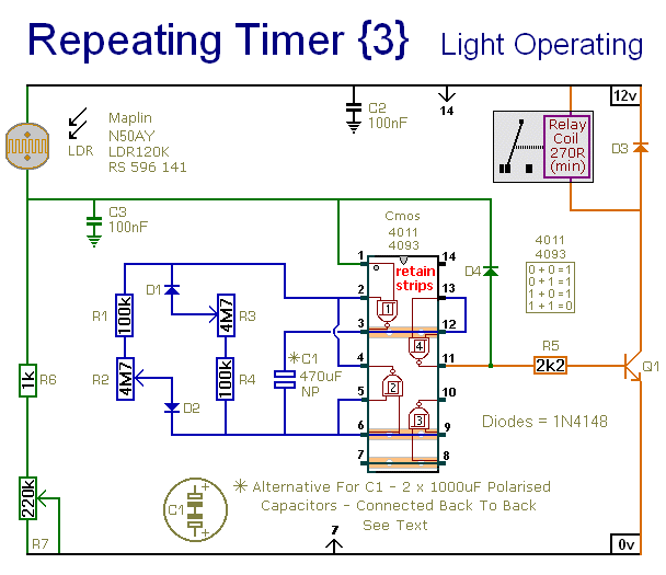
The circuit operates as a daylight-sensitive timer, leveraging the characteristics of an astable oscillator configuration. The LDR's resistance decreases with increasing light intensity, allowing for a customizable threshold for activation. The adjustment of R7 is crucial for fine-tuning the light sensitivity, ensuring that the timer only operates during the desired daylight conditions. The astable oscillator generates a square wave output, where the timing intervals are dictated by the RC time constant formed by R1, R2, and C1 for the on-time, and R3, R4, and C1 for the off-time.
The relay's operation is integral to the circuit's function, enabling the control of external devices based on the timer's output. The circuit's design accommodates a range of relay types, provided they meet the necessary specifications for voltage and current ratings. The use of non-polarized capacitors is essential for the stability of the oscillator, and the back-to-back configuration of polarized capacitors effectively achieves this requirement.
Power supply considerations are also important, as the circuit is adaptable to various voltage levels. When selecting the relay, it is advisable to ensure compatibility with the chosen power supply voltage, as this will influence the overall performance and reliability of the circuit. The comprehensive support materials provided facilitate the assembly and understanding of the circuit, ensuring successful implementation in practical applications.This circuit is very similar to Repeating Timer No. 2. However - the addition of the light dependent resistor means that the operation of this timer can be limited to the daylight hours. R7 lets you set the level of light at which the timer will stop. The type of LDR is not critical. The important thing is the voltage on pin 1. Any type of LDR sho uld work satisfactorily. But you may need to change the value of R7 - to achieve the desired range of adjustment. The circuit is basically an Astable Oscillator. And the output times depend on the value of C1 - and the speed at which it charges and discharges through the resistor network. The length of time the relay remains energized is controlled by R1 & R2. And the length of the time it remains de-energized is controlled by R3 & R4. The fixed resistors set the minimum period lengths - and the maximum period lengths are set by R2 & R3.
With the component values shown - both periods are adjustable from about 1 to 30 minutes. You can change the component values to suit your own requirements. If your time periods don`t need to be too precise - and more-or-less is close enough - you can leave out the pots altogether - and simply rely on R1 & R4 to set the times. Owing to manufacturing tolerances - the precise length of the time periods available depends on the characteristics of the actual components you`ve used - and a 4093 will produce longer time periods than a 4011.
Do not use the "on-board" relay to switch mains voltage. The board`s layout does not offer sufficient isolation between the relay contacts and the low-voltage components. If you want to switch mains voltage - mount a suitably rated relay somewhere safe - Away From The Board.
I`ve used a SPCO/SPDT relay - but you can use a multi-pole relay if it suits your application. When the oscillator is running - the polarity of the charge on C1 keeps reversing. So C1 needs to be non-polarised. However - you can simulate a non-polarised 470uF capacitor by connecting two 1000uF polarised capacitors back to back - as shown. How and why this works is explained in the Detailed Circuit Because non-polarised capacitors aren`t widely available - the prototype was built using two polarised capacitors.
The timer is designed for a 12-volt power supply. However - it will work at anything from 5 to 15-volts. All you need do is select a relay with a coil voltage that suits your supply. The Support Material for this circuit includes a parts list - a step-by-step guide to the construction of the circuit-board - a detailed circuit description - and more. 🔗 External reference
Related Circuits
The Olimex P-40 development board will be utilized, though the circuit can also be constructed on a breadboard due to its simplicity. The schematic for the initial implementation of servo control is provided below. Servos, like any motors, can...
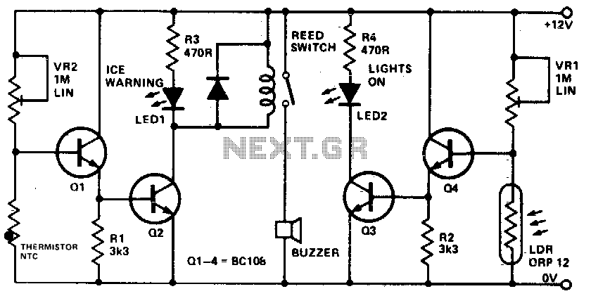
This device informs a driver whether their lights should be activated and warns them if the outside temperature approaches zero degrees Celsius by illuminating an LED and sounding a buzzer. The sensitivity can be adjusted using VR1, and the...
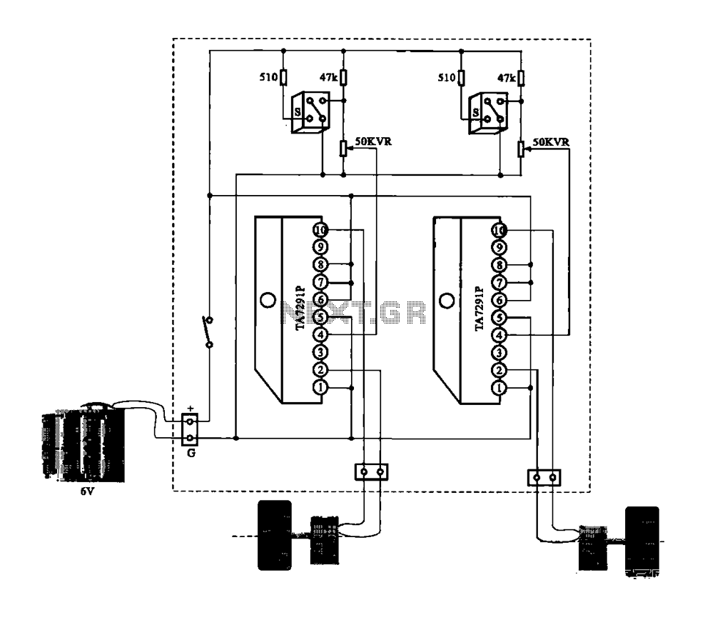
A dual motor drive circuit for automatic tracking consists of two motors that are part of a car structure, which operates based on the principles of a double motor drive system. The dual motor drive circuit is designed to facilitate...
The proximity detector detects the movement of PC board pieces as the wheel rotates, generating an output signal with a clear transition between high and low voltage levels, making it suitable for triggering counting or processing circuits. Following this...
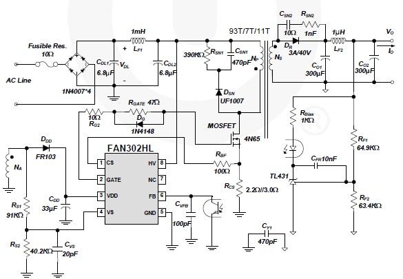
A simple 5-volt switching power supply electronic circuit project can be designed using the FAN302HL, a highly integrated PWM controller integrated circuit. This IC provides several features that enhance the performance of general flyback converters. The constant-current control of...
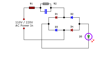
Compact yet highly functional, this is a straightforward and efficient LED circuit designed to operate directly from the AC mains supply, ranging from 100 volts to 230 volts. This LED circuit utilizes a few essential components to achieve efficient...