
Servo Motor Control Circuit
The described circuit utilizes the Olimex P-40 development board as a platform for controlling servos, which are critical components in various robotic applications. The schematic diagram illustrates the connection between the development board and the servos, with particular attention paid to power supply considerations. Given that servos can draw substantial current, it is advisable to select a power source capable of delivering sufficient current without voltage drop, especially when multiple servos are in operation.
The servos specified operate effectively within a voltage range of 4.8V to 6V, with a nominal supply of 5V being used in this implementation. This choice simplifies the circuit design while ensuring safe operation. The increased voltage supply can enhance the servos' torque, which is advantageous for applications requiring more force.
In scenarios where multiple servos are involved, the circuit design must accommodate simultaneous control. The schematic for controlling three servos demonstrates the use of pulse-width modulation (PWM) signals emitted from three designated pins on the development board—RB0, RB1, and RB2. Each pin corresponds to a specific servo, allowing for coordinated movement and control. The software controlling these pins must be designed to handle concurrent signals, which may involve implementing a timing mechanism to ensure that each servo receives the correct PWM signal at the appropriate intervals.
This setup is particularly beneficial in robotics, where multiple actions often occur simultaneously, necessitating precise control over each servo's position and movement. The integration of multiple servos into a single control scheme exemplifies the complexity and versatility required in robotic design, making it crucial to understand both the hardware and software components involved in such systems.Although we`ll be using the Olimex P-40 development board, you can also breadboard out the circuit as it is very simple. The schematic for our first pass at controlling a servo is shown below. Servos can start to sink alot of current like any motors so it is wise to be sure that your batteries can handle high currents.
Since we`re only using 1 or 2 servos, current won`t be an issue. You may have noticed that the servos we`re using are rated at 4. 8v & 6v. We`re hooking 5v to the servos in this tutorial just to make things easier. This will not harm the servos in any way. They can be safely operated between 4. 8 and 6 volts. The increase in voltage gives the servos more torque. One thing about robotics is that you are never ever doing only 1 thing at a time. When it comes to using servos in robotics it is very common that your project will have 2, 3 or even 4 servos that need to be operated at once. The multi servo schematic below is not very different from the single servo schematic above, but the software method for controlling the 3 servos simultaneously is intuitively different.
We`ll go over this in detail in the next section. 3 Pins are used to output control PWM signals to the 3 servos. RB0, RB1 & RB2. Don`t forget these names because in the next section we`ll see them again. 🔗 External reference
Related Circuits
This intelligent electronic lock circuit is constructed using only transistors. To unlock this electronic lock, the user must press tactile switches S1 through S4 in sequence. For added security, these switches can be labeled with different numbers on the...
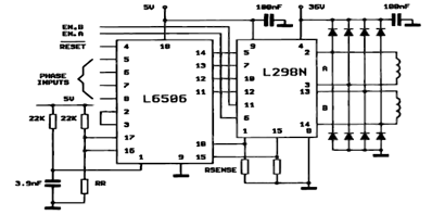
The following figure illustrates the control circuit for a two-phase bipolar stepper motor utilizing the current controller L6506. The L6506 integrated circuit generates the necessary signals to drive the inputs of the L298 bipolar stepper motor circuit driver. The circuit...
Each part of the LCD has an individual counter, latch, decoder, and driver. The pumping signal is fed back to the motherboard of the LCD. When the display section is disconnected, the phase and amplitude of the motherboard and...

Ceramic gas sensors can be utilized to analyze the content of alcohol vapor. With the appropriate sensor circuit, it is possible to detect blood alcohol content. The operating principle is straightforward: if blood alcohol content is present in a...
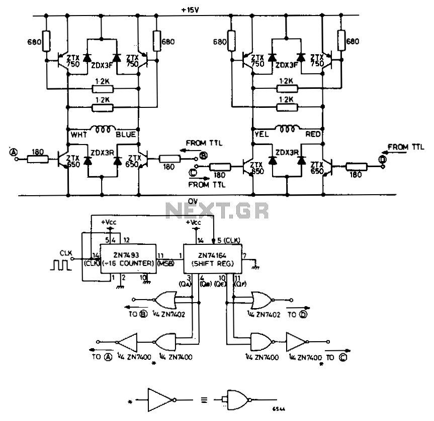
The circuit depicted in Fig. 62-15A is intended to drive a 15-V, two-phase, bipolar stepping motor, delivering a bidirectional single-level voltage across each winding with currents reaching up to 9.6 A. It comprises two identical transistor bridge stages that...
A 6V to 12V DC converter circuit is designed to convert a lower voltage of approximately 6 volts to a higher voltage of 12 volts, albeit with a reduced current rating. This inverter circuit can deliver up to 800mA...