
Mains Operated LED Circuit Schematic
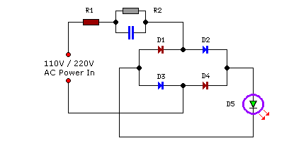
This LED circuit utilizes a few essential components to achieve efficient operation from a high-voltage AC source. The fundamental components include a bridge rectifier, a current-limiting resistor, and an LED or an array of LEDs.
The circuit begins with the AC mains input, which is connected to a bridge rectifier. The bridge rectifier consists of four diodes arranged in a specific configuration to convert the AC voltage into a pulsating DC voltage. This conversion is crucial as LEDs require a direct current (DC) to function properly.
Following the rectification process, a smoothing capacitor may be added to reduce the ripple in the output voltage, providing a more stable DC supply to the LEDs. The value of this capacitor should be chosen based on the load current and the desired ripple voltage.
To limit the current flowing through the LEDs, a current-limiting resistor is included in series with the LED. The resistor value can be calculated using Ohm's law, taking into account the forward voltage drop of the LED and the desired operating current. It is essential to select a resistor with an appropriate power rating to prevent overheating.
The LED or LED array is connected in parallel with the current-limiting resistor. Depending on the application, multiple LEDs can be connected in series or parallel to achieve the desired brightness and color output.
This circuit design is advantageous due to its simplicity and effectiveness in converting high-voltage AC power into usable light, making it suitable for various lighting applications where space is limited, yet high efficiency is required. Proper heat dissipation measures should also be considered to ensure the longevity of the components used in the circuit.Small in size! Big in use Here is a simple and powerful LED circuit that can be operated directly from the AC 100 volt to AC 230 Volts mains supply. The c.. 🔗 External reference
Related Circuits
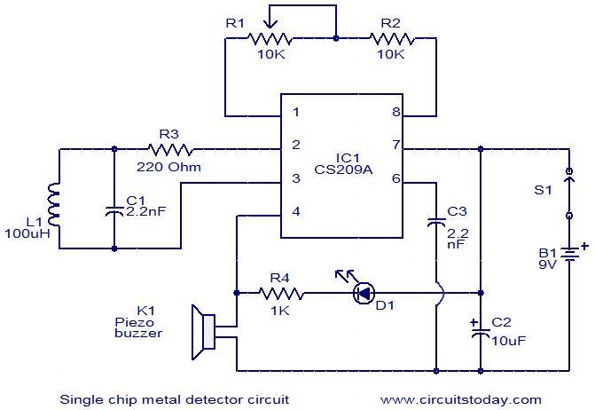
This is a simple single-chip metal detector circuit based on the IC CS209A from Cherry Semiconductors. A 100µH coil is utilized to detect the presence of metal. The IC CS209A incorporates a built-in oscillator circuit, with the coil (L1)...

A dimming control circuit generates a dimming control signal to determine the brightness of at least one light-emitting diode. The dimming control signal consists of multiple bright-dark cycles, each comprising a bright phase and a dark phase. The bright...

This circuit will impose a maximum slew rate on a signal; positive and negative rates can be independently controlled. The circuit is useful in servo applications where the error signal needs to be limited to be within the power...

The following circuit illustrates a schematic diagram for a remote control toy car. Features: it does not interfere with the performance of the original design. The remote control toy car circuit typically consists of several key components that enable wireless...

This circuit generates sine and square wave signals with frequencies ranging from below 20 Hz to above 20 kHz. The advantage of this circuit diagram is that the output frequency can be adjusted by varying the variable resistor R6. The...

This 555 timer clap switch circuit electronic project is designed using common electronic components. The circuit operates from a distance of up to 10 meters from the microphone. The signal from the microphone is amplified by transistors T1, T2,...