
10 Amp 13.8 Volt Power Supply circuit
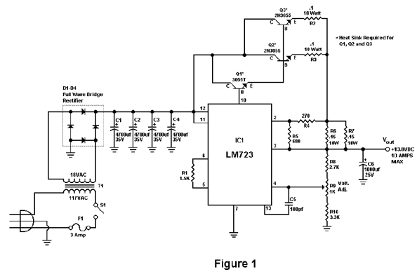
The circuit operates by utilizing a robust power supply capable of handling the specified surge current while maintaining stable performance under varying load conditions. The current limiting feature is achieved through a combination of resistive and active components that monitor the output current. When the current exceeds the predetermined threshold, the circuit automatically reduces the output, preventing potential damage to both the load and the power supply.
Key components of this circuit may include a high-current MOSFET or transistor, which serves as the main switching element, allowing for efficient control of the output current. A current sensing resistor is placed in series with the load to provide real-time feedback on the current flow. This feedback is processed by a control circuit, which could be implemented using an operational amplifier or a dedicated current sensing IC.
The design should also include protective elements such as fuses or circuit breakers to further enhance reliability and safety. Capacitors may be employed for filtering purposes, smoothing out voltage spikes and ensuring stable operation during transient conditions.
Overall, this circuit design not only meets the required current specifications but also emphasizes reliability and safety through its advanced current limiting mechanism.The circuit will give us amps (12 amps surge) with performance that equals or exceeds any commercial unit. The circuit even has a current limiting feature which is a more reliable system than most commercial units have..
🔗 External reference
Related Circuits
Instructions for creating a Clap-Clap On/Clap-Clap Off switch circuit. This guide provides the necessary information for constructing a clap-activated switch. The Clap-Clap switch circuit is an innovative design that utilizes sound activation to control electronic devices. The primary components of...
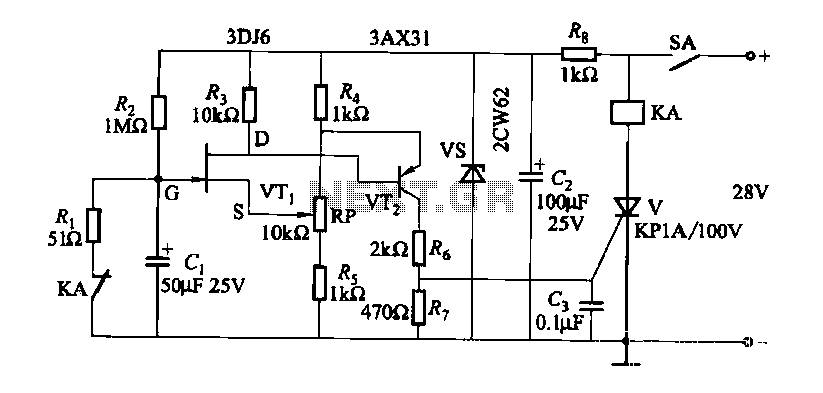
FET relay circuit 2 is essentially a JS-20 time relay circuit. When the switch SA is open, the relay device KA remains in the released state. Once switch SA is closed, the delay period begins. After a specified duration,...
The high and low voltage cut-off with delay and alarm circuit, along with its circuit diagram, is explained in this post. The high and low voltage cut-off circuit is designed to protect electrical devices from damage caused by excessive voltage...
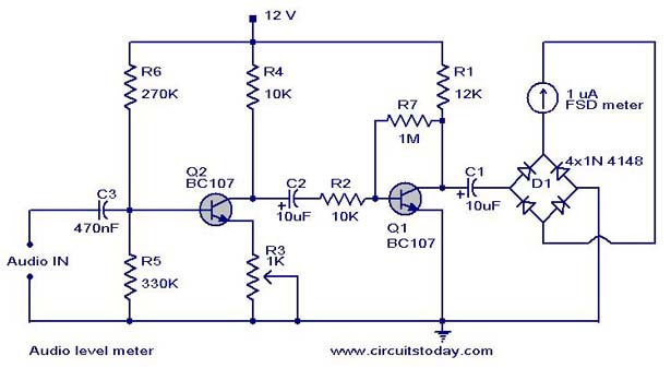
A simple audio level meter or Volume Unit (VU) level meter circuit with diagram and schematic. This sound level meter is designed using transistors with a flat frequency response in the range of 20Hz to 50kHz. The audio level meter...

A compact audio amplifier circuit utilizing the TDA 7052 integrated circuit from Philips. This circuit is suitable for use as a pocket radio amplifier, delivering an output power of 2 watts. The TDA 7052 is a low-voltage audio amplifier designed...

This circuit represents a negative resistance configuration. All previous circuits utilize RC time constants to achieve resonance. LC combinations can also be employed, providing good frequency stability, high Q factor, and rapid startup. In this circuit, a signal input...
Warning: include(partials/cookie-banner.php): Failed to open stream: Permission denied in /var/www/html/nextgr/view-circuit.php on line 713
Warning: include(): Failed opening 'partials/cookie-banner.php' for inclusion (include_path='.:/usr/share/php') in /var/www/html/nextgr/view-circuit.php on line 713