
sensors circuit
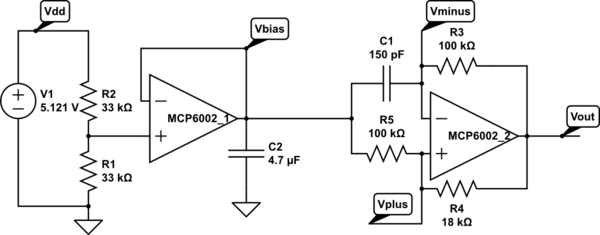
The touch sensor relaxation oscillator circuit consists of several key components: a 74HC14N Schmitt trigger inverter, a variable capacitor represented by a touch plate and the user's finger, and a resistor network that defines the timing characteristics of the oscillator. The Schmitt trigger inverter is essential for providing the necessary hysteresis, ensuring a clean transition between high and low states, which is crucial for reliable operation in the presence of noise.
The circuit operates by charging and discharging the variable capacitor through the resistor, creating a periodic waveform that can be measured to determine the frequency. The touch plate allows the user to influence the capacitance, thus altering the frequency of oscillation. The output from the Schmitt trigger is processed by the KL25Z microcontroller, which uses the custom interrupt service routine to accurately count the number of edges within a defined time frame, effectively averaging out any noise introduced by the touch sensor.
The design considerations for this circuit include the choice of resistor and capacitor values, which must be carefully selected to ensure that the oscillator operates within the desired frequency range while minimizing the impact of 60Hz interference. The system's sensitivity can be adjusted by altering the capacitor value; smaller capacitors increase sensitivity but also lead to higher frequencies, necessitating a balance between responsiveness and stability.
The integration of an RGB LED for visual feedback enhances the user experience, providing immediate indications of the circuit's status. This feature is particularly beneficial in educational settings, where students can quickly ascertain whether their circuit is functioning correctly or if adjustments are needed. Overall, this touch sensor relaxation oscillator circuit serves as an effective demonstration of capacitance measurement techniques and the impact of noise on electronic signals.Touch sensor Relaxation oscillator used in the hysteresis lab. The variable capacitor in this schematic is a person`s finger and a touch plate made from aluminum foil and packing tape. I spent today writing code for the KL25Z board to act as a period or frequency detector for the hysteresis lab, where they build a relaxation oscillator using a 74HC14N Schmitt trigger inverter
and use it to make a capacitance touch sensor (pictures of last year`s setup in Weekend work ). I had written code for the Arduino boards last year, and I started by trying to do the same thing on the KL25Z, using the MBED online development system. The Arduino code used PulseIn() to measure pulse duration, and the MBED system does not have an equivalent function.
I could have implemented PulseIn() with a couple of busy waits and a microsecond-resolution timer, but I decided to try using InterruptIn to get interrupts on each rising edge instead. The basic idea of last year`s code (and the first couple versions I wrote today) was to determine the pulse duration or period when the board is reset, finding the maximum over a few hundred cycles, and using that as a set point to create two thresholds for switching an LED on or off.
I got the code working, but I was not happy with it as a tool for the students to use. The biggest problem is that the touch plate couples in 60Hz noise from the user`s finger, so the oscillator output signal is frequency modulated. This frequency modulation can be large compared with the change in frequency from touching or not touching the plate (depending on how big C1 is), so setting the resistor and capacitor values for the oscillator got rather tricky, and the results were unreliable.
I then changed from reading instantaneous period to measuring frequency by counting edges in a 1/60th-second window. That way the 60Hz frequency modulation of the oscillator gets averaged out, and we can get a fairly stable frequency reading.
The elimination of the 60Hz noise allows me to use less hysteresis in the on/off decision for the LED, making the touch sensor more sensitive without getting flicker on transitions. The code worked fairly well, but I was not happy with the maximum frequency that it could handle ”the touch sensor gets more sensitive if C1 is small, which tends to result in high frequency oscillations.
The problem with the code was that MBED`s InterruptIn implementation seems to have a lot of overhead, and the code missed the edge interrupts if they came more often than about every 12 µsec. Because I was interrupting on both rising and falling edges, the effective maximum frequency was about 40kHz, which was much lower than I wanted.
To fix the frequency limitation, I replaced MBED`s InterruptIn with my own interrupt service routine for PortD (I was using pin PTD4 as the interrupt input). With this change, I could go to about 800kHz (1. 6e6 interrupts per second), which is plenty for this lab. If I wanted to go to higher frequencies, I`d look at only rising edges, rather than rising+falling edges, to get another factor of two at the high end.
I didn`t make that change, because doing so would reduce the resolution of the frequency measurement at the low end, and I didn`t think that the tradeoff was worth it here. The code is now robust to fairly large variations in the oscillator design. It needs a 20% drop in frequency to turn on the green LED, but the initial frequency can be anywhere in the range 400Hz 800kHz.
To make it easier for students to debug their circuits, I took advantage of having an RGB LED on the board to indicate the state of the program: on reset, the LED is yellow, turning blue once a proper oscillator input has been detected, or red if the oscillator frequency is not in range. When the frequency 🔗 External reference
Related Circuits
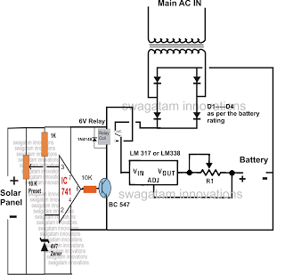
The automatic changeover relay circuit was requested by Mr. Karimulla Baig. The circuit is designed to charge a connected battery at a constant current using power from a solar panel. In the absence of solar energy, such as during...
This circuit utilizes an LM339 quad voltage comparator to create a time delay and manage a high current output at low voltage levels. Approximately 5 amps of current can be achieved using two fresh alkaline D batteries. Three of...
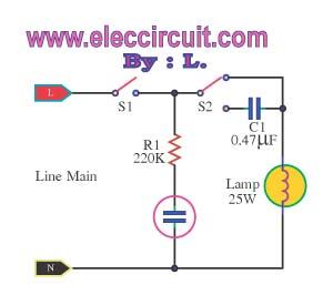
This is an automatic light dimmer circuit that eliminates the need for manual adjustment of light levels. It utilizes a Light Dependent Resistor (LDR) to detect ambient light conditions, which in turn controls a Triac to adjust the brightness...

This type of charger transfers RF energy from an inductor (L2) to an external pickup coil. The pickup coil is connected to a rectifier and a battery that requires charging. This design is advantageous as it eliminates the need...
When the lights of an oncoming car are detected by the photo-transistor Q1, the circuit activates. Sensitivity is adjusted by the 22-megohm resistor, R5, to approximately half a foot-candle. The relay employed has a 12-volt, 0.3A coil. The L14C1...
The discharge control circuit consists of a battery management system designed to prevent over-discharge of a battery. It features a relay control mechanism that activates when the battery voltage drops below a specified threshold of approximately 10.5V. The circuit...