
Opto-Coupled Discrete Pulse Stretcher
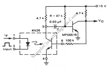
The pulse stretcher circuit is designed to elongate the duration of an incoming pulse signal, which is particularly useful in digital signal processing applications where signal timing is critical. The use of the 4N26 optocoupler provides electrical isolation between the input and output, enhancing safety and reducing noise interference from the input signal.
In this configuration, the pulse stretcher operates by first detecting the incoming pulse through the input terminal, which is connected to the LED side of the optocoupler. When the LED is activated by the incoming pulse, it generates a corresponding output signal on the phototransistor side of the optocoupler. The output from the phototransistor is then fed into a one-shot circuit, typically implemented using a monostable multivibrator, which produces a pulse of a predetermined width regardless of the duration of the input pulse.
The one-shot circuit can be adjusted to set the desired pulse width, allowing for flexibility in various applications. The output pulse can be further processed or utilized in other digital circuits, ensuring that the timing requirements are met.
Overall, this pulse stretcher circuit is an effective solution for extending pulse durations while maintaining signal integrity and isolation, making it suitable for a wide range of electronic applications.This is a pulse stretcher circuit using optocoupler. This circuit uses a 4N26 opto-coupler combined with a standard one-shot circuitry. This circuit is.. 🔗 External reference
Related Circuits
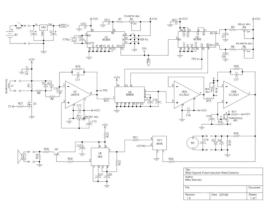
As you can see, there is only one regulated 12 volt supply operating the entire circuit. This allowed me to adjust the offset within an operating window. By using a tantalum capacitor of reasonably high capacity, the signal passes...
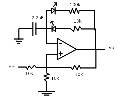
The relaxation oscillator generates a relatively consistent square wave. By altering the duty cycle, the effect can be visualized using LEDs. The following variation of the relaxation oscillator circuit can be assembled. The relaxation oscillator circuit typically consists of a...
If you have ever wanted a high-voltage generator to create impressive lightning effects, conduct Kirlian photography experiments, or experiment with neon lights, this project is ideal. It describes a laboratory pulse generator utilizing an auto-ignition coil, capable of delivering...
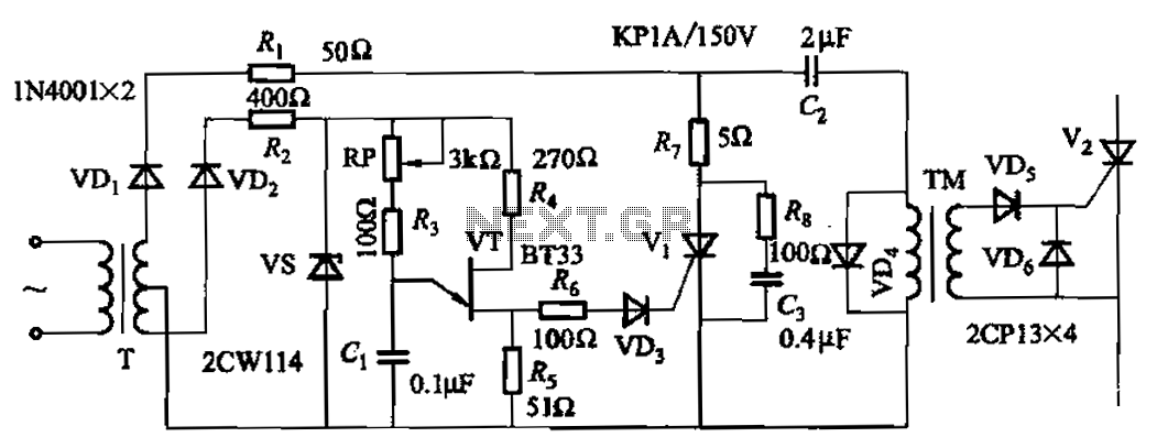
The adjustment potentiometer RP allows for modification of the pulse phase shift range, which spans from 0 to -1600, providing higher sensitivity. The circuit incorporating the adjustment potentiometer RP is designed to facilitate precise control over the phase shift of...
A monostable multivibrator circuit generates a fixed pulse width when triggered by an input signal. The input is connected to CR1, which should be configured as an open collector source, as TR1 will short the input to ground during...
A marker oscillator can be constructed using an NE555 timer to generate pulses at an audio frequency. This design facilitates the identification of signals amidst interference. The oscillator can utilize a crystal with a frequency ranging from 1 to...
Warning: include(partials/cookie-banner.php): Failed to open stream: Permission denied in /var/www/html/nextgr/view-circuit.php on line 713
Warning: include(): Failed opening 'partials/cookie-banner.php' for inclusion (include_path='.:/usr/share/php') in /var/www/html/nextgr/view-circuit.php on line 713