
A New Solar / Wind Charge Controller Based on the 555 Chip
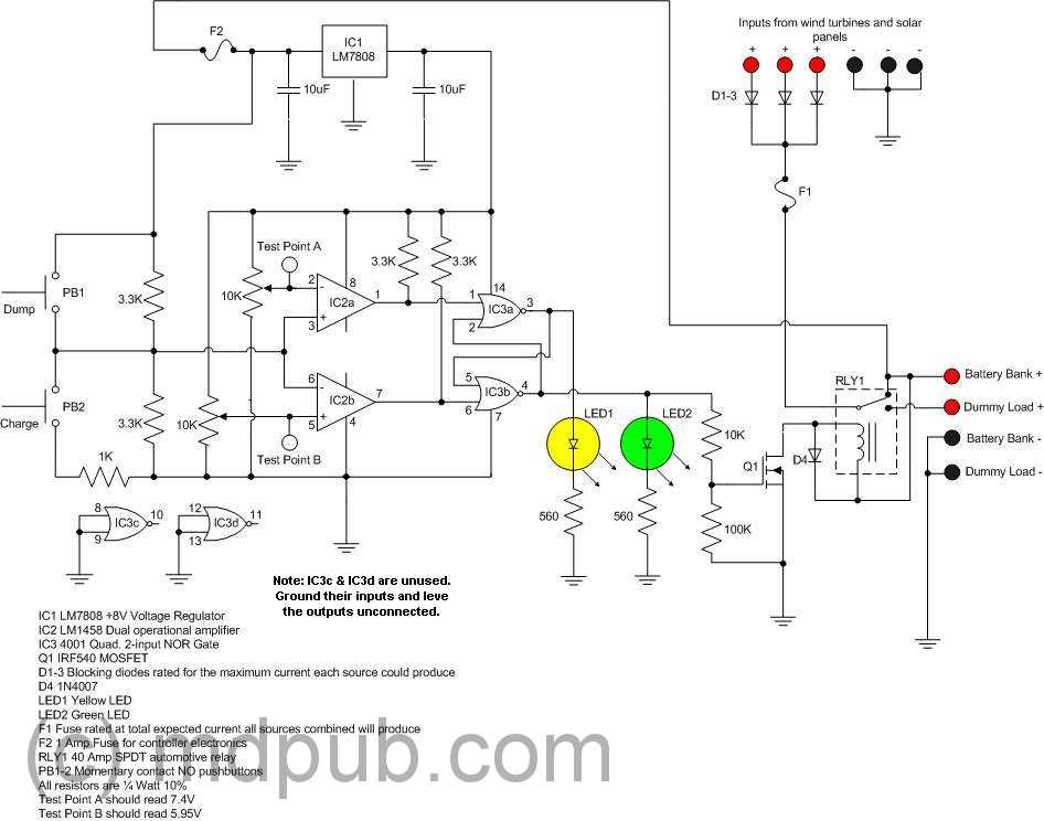
The circuit design centers around a charge controller that effectively manages power distribution between battery storage and load applications, particularly for renewable energy sources like solar panels and wind turbines. The use of the 78L05 voltage regulator ensures that the circuit receives a stable 5V supply, critical for the reliable operation of control electronics. The choice of components, including the use of a relay, allows for high-current switching, accommodating loads up to 40 Amps, which is essential for applications involving significant power draw.
The calibration process is crucial for ensuring that the controller operates correctly within the defined voltage thresholds. By adjusting resistors R1 and R2, the circuit can be fine-tuned to switch accurately between charging the batteries and diverting excess energy to a dummy load. This capability is particularly important for optimizing battery life and performance, as it prevents over-discharging and ensures that batteries are charged efficiently.
The enclosure design, while not ideal for permanent outdoor installation, provides adequate protection during field testing. The use of a barrier strip simplifies connections and enhances the overall reliability of the system by reducing the risk of loose or faulty connections. The inclusion of a fuse adds an additional layer of safety, protecting the circuit from potential overcurrent situations.
Overall, this charge controller design exemplifies a practical approach to managing renewable energy sources, emphasizing both functionality and ease of use in field applications.I had the prototype working on the breadboard, I built another unit on a piece of Radio Shack Protoboard for use in the field. It came together in only a couple of hours, and again, worked the first time (I must be living right lately).
This more rugged version will get mounted in a box and given a thorough testing in the field. Note that onthis board I have chosen to use the 78L05 version of the 5 Volt regulator. It is in a tiny TO-92 package, the same size as the 2N2222 transistor. It is the small, black rectangle on the upper left corner of the board. It saves a lot of board space. It can only handle 100 mA, but that is plenty enough to power this circuit. If you can`t find the little 78L05, you can use the full size TO-220 version of the 7805, which is much more common. There will be no penalty other than using up a little more board real estate. I just happened to have a few of the 78L05s left over from another project. Once you have the circuit built, it is time to tune or calibrate it. I use 11. 9V and 14. 9V as my low and high set points for the controller. These are the points where it switches from sending power to the batteries to dumping power into a dummy load, and vice versa (a dummy load is only needed if you are using a wind turbine, if using only solar panels, the dummy load line can be left open).
Probably the best way to tune the circuit is to attach a variable DC power supply to the battery terminals. Set the power supply to 11. 9V. Measure the voltage at Test Point 1. Adjust R1 until the voltage at the test point is as close to 1. 667V as you can get it. Now set your variable power supply to 14. 9V and measure the voltage at Test Point 2. Adjust R2 until the voltage at the test point is as close to 3. 333V as you can get it. Test the operation of the charge controller by running the input voltage up and down between about 11.
7 and 15. 1 Volts. You should hear the relay pull in at about 14. 9 Volts and open at about 11. 9 Volts. In between the two set points the controller should stay in whichever state it is in. The Charge and Dump buttons can be used to change the state of the controller when the input Voltage is between the two set points. Before you write to me and tell me that my lower set point is too low and I am over-discharging my batteries, consider that the battery voltage isn`t normally going to get that low except under load.
If the load were removed, the voltage would recover over time back up to well over 12V. So the batteries aren`t as deeply discharged as you might think at first glance. Once I had the circuit working, I mounted it inside a semi-weatherproof enclosure. The relay is on the left side. I used a barrier strip to make wiring everything together easier. I used heavy gage wire for all the high-current connections. This thing was designed to switch up to 40 Amps after all. I also included a fuse in line with the solar/wind input line. Here is another view with the lid in place. I used this enclosure because I happened to already have it on hand, not because it is the best one for the job. For permanent outdoor use I would prefer to use a more rugged and weather-proof enclosure like I did for my original charge controller design.
However, I like the fact that I can see the LEDs through the translucent lid and tell which state the charge controller is in at a glance, and I didn`t have to drill any extra holes in the box for the LEDs. This box will work for field testing purposes. Here is a side view of the unit showing the feed-through barrier strip with all the connections to the outside.
There are connections for the positive side of the battery(s), the positive input from a solar panel or wind turbine, the positive side of an optional dummy load, and three ground connections. When hooking up the charge controller, the battery should be connected first. That way the electronics will have a stable source of power 🔗 External reference
Related Circuits
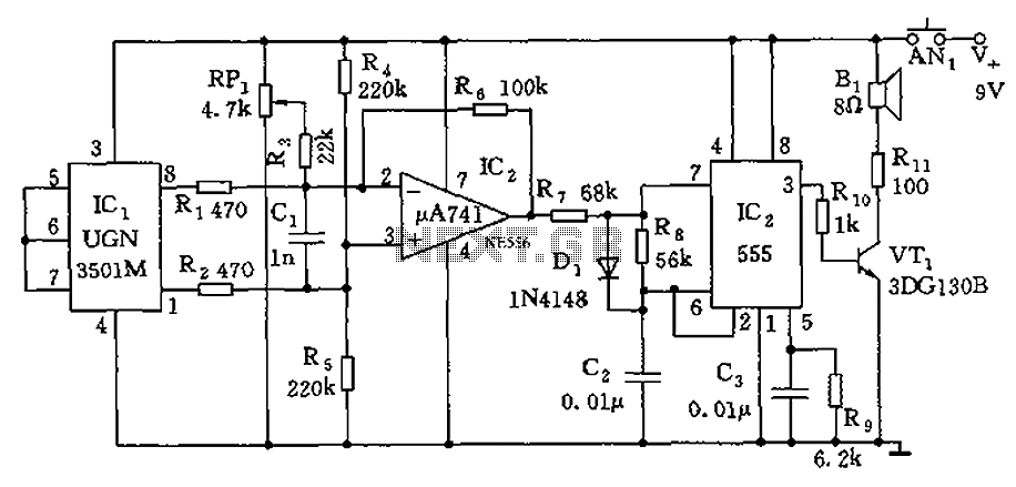
The circuit consists of a 555 timer and associated components designed for voltage-to-frequency conversion. It is utilized for determining the orientation of Earth's magnetic field using a Hall-effect sensor, specifically the UGN-3501M. This sensor incorporates a Hall element and...
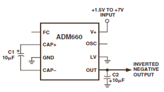
The ADM660 is a charge-pump voltage converter that can either invert the input supply voltage or double it. The schematic below depicts the ADM660 Voltage Inverter Circuit Configuration Diagram. This inverting schematic is ideal for generating a negative rail...
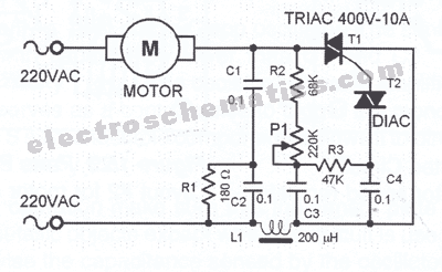
This triac-based 220V AC motor speed controller circuit is designed for controlling the speed of small household motors, such as drill machines. The motor speed can be adjusted by altering the setting of P1, which determines the phase of...
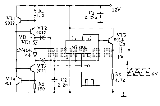
The circuit depicted involves transistors VT1, VT2, and resistor R1, which form a constant current source for charging capacitor C2 in a linear manner. Transistors VT3, VT4, and resistor R2 create a constant current source for discharging capacitor C2,...
This document provides a circuit diagram of a car stereo. It includes a circuit diagram of a Class B 15 Watts audio amplifier designed using a dual op-amp and a transistor. The 15 W Class B audio amplifier circuit...
This circuit enables the testing of a servo motor. The angle of the servo can be adjusted using a 10k potentiometer. It is possible that not all positions can be achieved with this circuit; experimenting with different resistors may...