
ADM660 Charge Pump Voltage Inverter Circuit Configuration and Datasheet
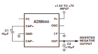
The ADM660 is a versatile charge-pump voltage converter capable of performing both voltage inversion and doubling functions. It operates effectively in applications where a negative voltage rail is required, particularly in single-supply systems. The circuit configuration typically consists of a few essential components: the ADM660 IC itself, capacitors for charge storage, and external connections for input and output voltages.
The device's ability to invert or double the input voltage is facilitated by its internal charge pump circuitry, which utilizes capacitors to transfer charge efficiently. The inclusion of a Frequency Control (FC) input pin allows for fine-tuning of the operating frequency, which can enhance performance by optimizing the size of the capacitors used in the circuit while maintaining low quiescent current levels. This is particularly beneficial in battery-operated devices where power efficiency is critical.
The ADM660 is suitable for a wide range of applications, including portable electronics, where space and power constraints are paramount. It is also applicable in remote data acquisition systems, where stable and reliable power supplies are necessary. Furthermore, the device can be utilized to power operational amplifiers that require dual supply voltages.
In designing a circuit with the ADM660, it is essential to follow the recommended guidelines outlined in the datasheet. This includes selecting appropriate capacitor values to achieve the desired voltage conversion and ensuring that the input voltage levels are within the specified range for optimal performance. Overall, the ADM660 provides a compact and efficient solution for voltage conversion needs in various electronic applications.The ADM660 is a charge-pump voltage converter that can be used to either invert the input supply voltage or double it. The schematic below appearsADM660 Voltage Inverter Circuit Configuration Diagram. This inverting schematic is ideal for generating a negative rail in single power supply systems. In order to optimize capacitor size and quiescent c urrent, there is a Frequency Control (FC) input pin instead of the external oscillator (OSC) pin, according to the datasheet. This device used to be applied in applications such Handheld Instruments, Portable Computers, Remote Data Acquisition and Op Amp Power Supplies.
See complete read on thisCharge Pump Voltage Inverter Devicein the ADM660 Datasheet (source: analog. com). 🔗 External reference
Related Circuits
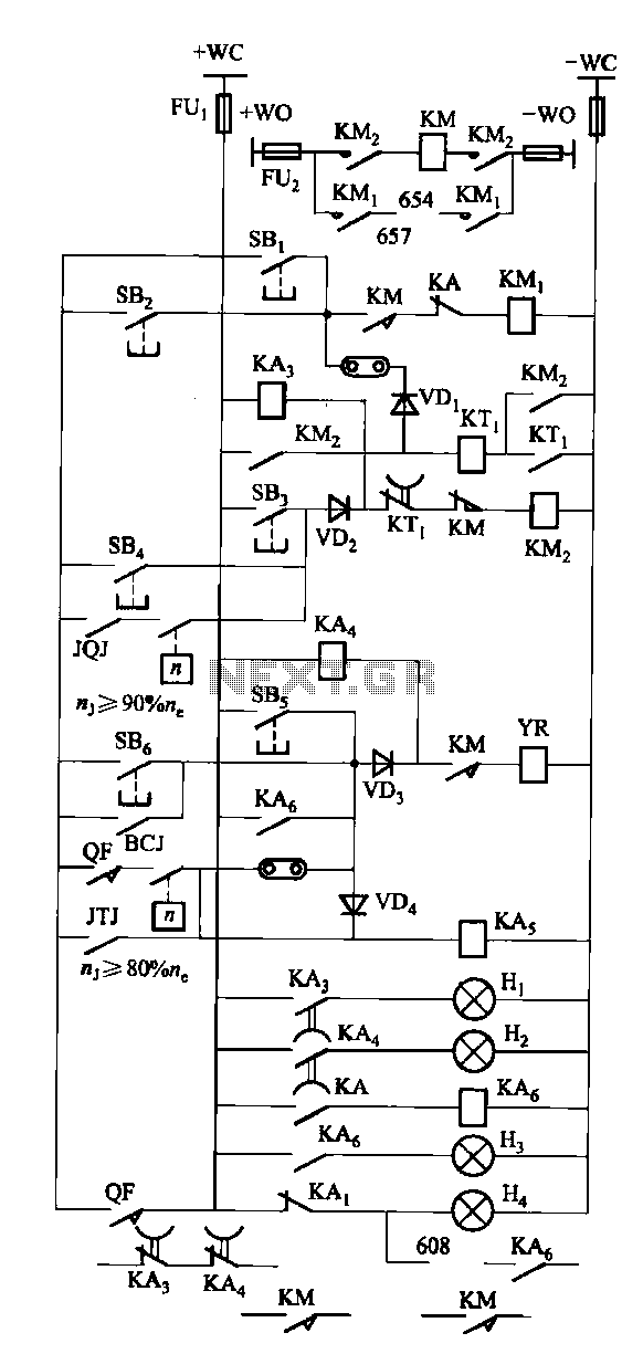
The FKL-32 type automatic thyristor excitation device is designed for synchronous generators with a terminal voltage of 400V and a capacity of 500kW and below. It is used for the automatic adjustment of excitation. The FKL-32 thyristor excitation device is...
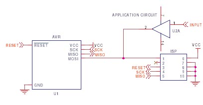
It is crucial to design the PCB layout correctly to enable seamless In-System Programming (ISP) of AVR microcontrollers. This guide addresses common issues encountered and provides typical AVR ISP circuit schematics. It focuses on Serial Programming, known as ISP,...

These two comparators function as over-voltage and under-voltage comparators. In the first configuration, if the measured voltage (Vm) exceeds the reference voltage, the output of IC1 goes low. In the second configuration, if the input voltage (ViN) exceeds the...
The mixer features two stereo phono inputs and two stereo line-level inputs, along with one stereo bonded channel. It also includes a microphone input and a stereo output with adjustable gain. The mixer is designed to accommodate a variety of...
There are monitors that feature only three BNC inputs and utilize composite synchronization (sync on green). This circuit has been specifically designed for such monitors. The design maintains simplicity while delivering reasonable performance. The operational principle is straightforward. The...
When the power supply reaches the circuit and the input signal is applied, the sound signal is processed through capacitor C1 and resistor R1 for signal coupling and noise reduction. The modified signal then reaches pin 3 (non-inverting) of...