
Simple servo controller Schematic
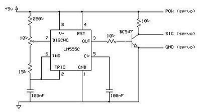
The described circuit for testing a servo motor primarily utilizes a 10k potentiometer, which serves as a variable resistor to control the angle of the servo. The circuit typically includes a power supply, a microcontroller or a servo driver, the servo motor itself, and the potentiometer. The potentiometer is connected to an analog input of the microcontroller, allowing the user to adjust the voltage level based on the position of the potentiometer.
The microcontroller reads the voltage from the potentiometer and translates it into a corresponding angle for the servo motor. The servo motor is designed to move to a specific position based on the input signal it receives, which is often a Pulse Width Modulation (PWM) signal. The width of the pulse determines the angle to which the servo will turn.
In cases where the servo does not reach the desired positions, it may be necessary to modify the resistance values in the circuit. This can be achieved by replacing the 10k potentiometer with one of a different value or by adding additional resistors in series or parallel to fine-tune the voltage range sent to the microcontroller. Adjusting the resistor values may help accommodate different types of servos or specific application requirements.
In summary, this circuit is a practical tool for testing servo motors, allowing for precise control over their angle of movement through the use of a potentiometer. However, users should be prepared to experiment with different resistor configurations to optimize performance for various types of servos.This cicuit allows you to test a servo. The angle of the servo can be set by means of the 10k potmeter. Perhaps you will not be able to reach all positions with this circuit. Playing with other resistors may help. 🔗 External reference
Related Circuits
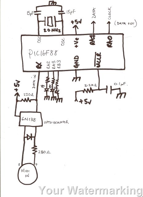
A code has been developed to process MIDI data received on the RX pin of the USART. It stores three bytes of data in a buffer, checks the first byte to determine if it is a MIDI "on" message...
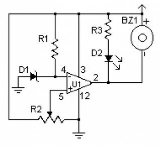
This simple circuit tests speakers, microphones, transformers, and voltage. It is essentially a very low-frequency oscillator that produces extremely short pulses. The sound produced is easy to hear and helps determine the precise direction it originates from, making it...
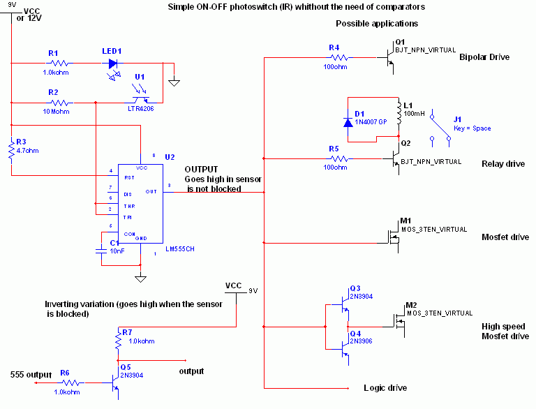
When the phototransistor is illuminated by infrared (IR) light, it begins to conduct, causing the voltage between a 1 MΩ resistor (chosen arbitrarily) and the phototransistor to decrease from VCC to lower values. When this voltage falls below VCC/3,...
The difference between these two ICs. A microcontroller is a specialized type of microprocessor designed to be self-sufficient and cost-effective, while a microprocessor is typically intended for general-purpose use, such as in personal computers (PCs). The microcontroller integrates several...
A low voltage monitor circuit is essential for security and protection against potential damage to equipment, particularly for vehicles. This circuit is relatively simple to construct, utilizing the LM339 integrated circuit. The operation of this circuit involves activating a...
The circuit receives its input from the zero-crossing detector, which generates a 0-to-1-to-0 pulse to set the R-S flip-flop and activate the ramp circuit (A to Ramp) to initiate the timing ramp ascent. The described circuit operates by utilizing a...
Warning: include(partials/cookie-banner.php): Failed to open stream: Permission denied in /var/www/html/nextgr/view-circuit.php on line 713
Warning: include(): Failed opening 'partials/cookie-banner.php' for inclusion (include_path='.:/usr/share/php') in /var/www/html/nextgr/view-circuit.php on line 713