
555 Audio guide blind electronic circuit diagram
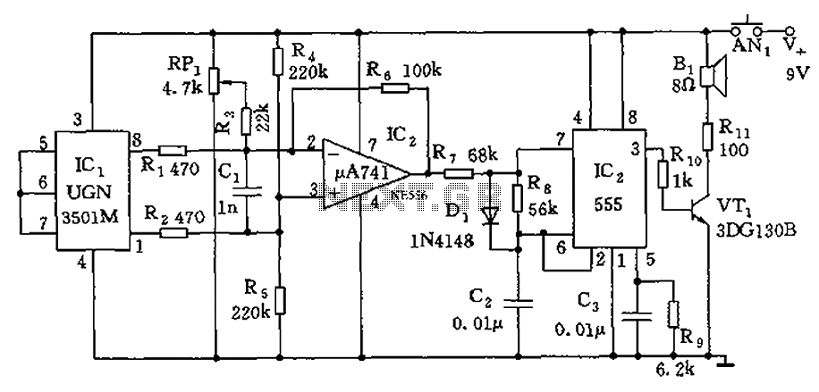
The circuit operates by utilizing the 555 timer in astable mode, where it generates a square wave output based on the charging and discharging cycles of capacitor C2. The frequency of this output is determined by the values of resistors connected to the discharge pin and the capacitor itself. The Hall-effect sensor detects the magnetic field and provides a voltage output proportional to the field strength, which is then amplified by the uA741 operational amplifier. The differential output from the sensor is critical for accurately measuring the magnetic field, as it allows for noise reduction and improved sensitivity.
The configuration of the Hall sensor with the flat magnets ensures that the sensor is aligned optimally to detect the magnetic field lines, thereby enhancing the overall performance of the circuit. The adjustment of potentiometer RP1 plays a vital role in calibrating the circuit, allowing for fine-tuning based on the specific application and environmental conditions. This capability is essential for applications requiring precise orientation detection, such as in navigation systems or robotic guidance. The output from the 555 timer can be used to drive a speaker or other sound-producing device, providing audible feedback on the orientation based on the frequency modulation. This design approach effectively combines analog signal processing with practical applications in orientation detection and navigation. As shown, the 555 and the surrounding elements constitute a voltage - frequency conversion circuit. For determining the orientation of Earths magnetic field is a Hall-effect de vices integrated sensor UGN-3501M, The sensor contains a Hall element and a linear differential amplifier, the sensitivity of the device is about 1.4 mV/gauss, improve measurement Earths magnetic field sensitivity on both sides of the sensor against the two flat magnets to pick up the subject of Earths magnetic field lines more. Differential output of the sensor (1 feet, 8 feet), respectively uA741 consisting of the differential amplifier inverting terminal (pin 2) and a non-inverting terminal (pin 3) is connected to further enlarge and then added to 555.
IC2 magnitude of the output voltage depends on the pickup device Hall magnetic field strength, and the voltage component 555 - the frequency converter output frequency of the pulse height depends on the charge voltage value C2, that is, the output frequency is low the orientation guide sounder which to decide. When adjusted by adjusting potentiometer RP1, so that when the magnetic field is zero, the pulse frequency of 555 to a certain value (eg 1000Hz), when the position changes due to changes in the magnetic field causes the frequency changes, the blind can be varied according to pitch determining the orientation of walking.
Related Circuits
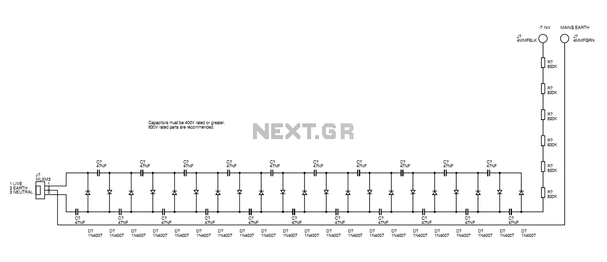
A basic mains driven Cockroft ladder high voltage generator is shown in the schematic. This is functionally the same as a project in Electronics Today International many years ago. The peak mains voltage of 340V appears across each capacitor...
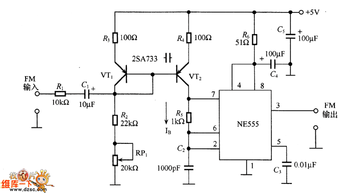
The figure illustrates an NE555 frequency modulation (FM) circuit. In this circuit, pin 7 of the NE555 is connected to an FM modulation section that consists of resistor R5 and capacitor C2, although the frequency range is somewhat limited....
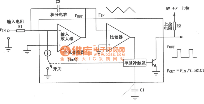
The VFC62 is a voltage-to-frequency and frequency-to-voltage converter that effectively transforms analog signals into digital signals. The digital output is presented in an open collector format, where the digital pulse repetition rate is directly proportional to the amplitude of...
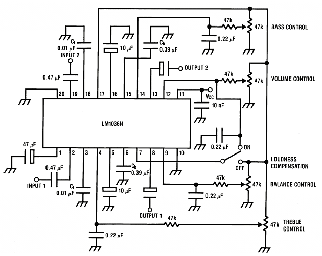
The LM1036 is a DC-controlled circuit designed for tone (bass/treble), volume, and balance adjustments in stereo applications, including car radios, televisions, and audio systems. It features an additional control input for easy loudness compensation. The circuit includes four control...
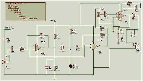
Mark Harrington Audio Tracer. The audio input is fed into the first stage op-amp via C6, RV1, C4, and R4. The Mark Harrington Audio Tracer is a specialized audio processing circuit designed to enhance and analyze audio signals. At its...
The W7800 is a positive integrated voltage regulator, while the F007 consists of an operational amplifier used in a power supply tracking application circuit. Some configurations utilize both positive and negative power supplies, with a negative supply necessary to...