
A on-shot circuit ideals

The One-Shot circuit, or monostable multivibrator, is a fundamental digital circuit that produces a single output pulse of a defined duration when triggered by an external event. This circuit typically consists of a timing resistor, a timing capacitor, and a logic gate or flip-flop configuration that defines its behavior.
When the input signal transitions from low to high, the circuit is triggered, causing the output to switch to a high state for a predetermined time period. The duration of the output pulse is primarily determined by the values of the resistor and capacitor used in the timing circuit, following the formula T = 1.1 * R * C, where T is the time period, R is the resistance, and C is the capacitance.
Common applications of the One-Shot circuit include pulse width modulation, timer applications, and event debouncing in digital systems. It is widely utilized in various electronic devices for generating precise timing sequences and controlling the timing of events. The versatility and simplicity of the One-Shot circuit make it an essential component in digital electronics design.
In practical implementations, the circuit may be constructed using discrete components such as resistors, capacitors, and transistors, or integrated into a single package using dedicated monostable multivibrator ICs. The choice of components and configuration will depend on the specific requirements of the application, including pulse duration, power consumption, and response time.The digital circuit additional a circuits taht is very useful is On-Shots circuit or Also known as Mono-stable multivibrator circuit. This behavior is the.. 🔗 External reference
Related Circuits

This schematic is directly sourced from the Altera ByteBlaster datasheet or manual, which provides comprehensive details regarding the connector's functionality and pin connections. It is advisable to review the datasheet available on their website or through a search engine...

This voltmeter utilizes a pair of JFETs in a balanced-bridge source-follower amplifier circuit. Q1 and Q2 should be matched within 10% for IDSS. This configuration minimizes meter drift and maintains bridge balance over temperature. The described voltmeter is an advanced...

The TDA1029 is a dual operational amplifier configured as an impedance converter. Each amplifier features four mutually switchable inputs that are safeguarded by clamping diodes. Signal sources can be switched in various modes. The electronic components required for this...

Figure 3173 illustrates a control circuit for a wound rotor induction motor that enables mechanical braking, dynamic braking, and reverse braking functions. The circuit includes various components such as relays, contactors, and time relays to manage the motor's speed...
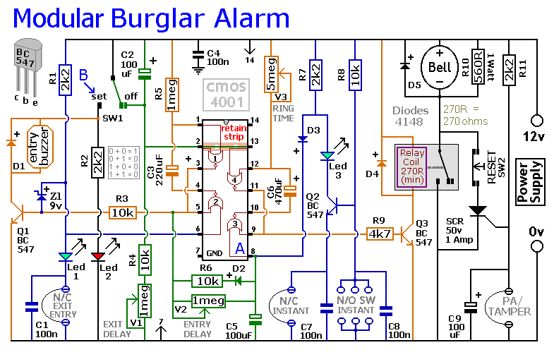
This circuit includes automatic exit and entry delays, as well as a timed bell cut-off feature. It supports both normally-closed and normally-open contacts, and incorporates a 24-hour personal attack/tamper zone. The use of expansion modules allows for the addition...

This is the power diagram for motor forward and reverse operation. To change the motor direction, one polarity must be altered, for example, changing R to S. For detailed information, please refer to the following. The described power diagram illustrates...