
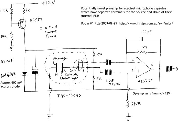
A potentially novel pre-amp for electret mic capsules which have their internal FETs Drain and Source connections available separately
The circuit design focuses on optimizing the performance of electret microphones by employing a preamplifier configuration that enhances sensitivity and reduces noise. The arrangement allows for the integration of external FETs, which can be beneficial in applications where the inherent noise of a single FET becomes a limiting factor. By parallelizing multiple FETs, the overall noise performance can be improved, thereby enhancing the signal-to-noise ratio of the microphone output.
The Linkwitz modification serves as a pivotal enhancement for electret microphones, allowing for better control of the biasing conditions and improved access to the FET's Source and Drain terminals. This modification can facilitate more precise adjustments to the microphone's performance characteristics, particularly in high SPL environments where traditional configurations may struggle.
In addition to the physical characteristics of the microphone capsule, attention must be given to the electrical characteristics of the FETs used in the circuit. The choice of FET, such as the 2SK1109, is crucial for achieving the desired electrical performance. The design must account for the inherent diode characteristics of the FET, as well as the need for stabilization of the Gate voltage through appropriate resistor configurations or external components.
Furthermore, the circuit should be designed with attention to the layout and connections to minimize parasitic capacitances and inductances, which can adversely affect performance. Careful consideration of the grounding scheme and the routing of signals will contribute to the overall fidelity of the microphone system.
Testing and validation of the circuit will involve measuring frequency response, background noise levels, and conducting listening tests to assess performance under various conditions. These evaluations will provide critical feedback for further refinements and optimizations of the preamplifier design, ensuring that it meets the specific requirements of high-quality audio applications.This circuit might also be of interest to people making pre-amps for electret and externally polarized condenser microphones which have no internal FET. (If a single FET`s noise is the limiting factor, perhaps two or four could be run in parallel. ) Some "two terminal" electret microphones can be modified to provide separate access to the Source an
d Drain of the internal FET. This, together with a new arrangement for biasing the modified capsule, is known as the "Linkwitz modification" (Linkwitz mod) and was first developed, or at least first made widely known, by Siegfried Linkwitz : The test arrangements are not necessarily very accurate in terms of absolute sound levels - I was using a cheap sound meter. I guess they are accurate within a few dB SPL. The tests were purely of 1kHz at sound levels between 110 dB SPL and 140 dB SPL. I have not yet measured frequency response or background noise. Nor have I yet done any listening tests. They are 14mm in diameter. They are a "back electret" design with a layer of charged fluoropolymer (I assume) on the front of the backplate.
The diaphragm is 3 um thick aluminized mylar (I assume) with the aluminization layer, which is grounded, on the front. At the back we have Ground, Source and Drain. For the capsule at the lower right of the above photo, the Ground is the gold-plated tracks, the Drain is to the upper left and the Source is to the lower right.
The only access to the backplate we have is through the gate of the FET - so we have to do everything via the FET`s Source and Drain. We need to get to know this device as well as possible. This does not appear to be one of the FETs in current production at NEC. The current ones have rather similar specifications. Maybe this pre-amp design will work just as well with FETs other than the 2SK1109. (Thanks to Richard Crowley of the Micbuilders list who told me that the FET`s only markings - "J34" - mean it is probably a 2SK1109.
) I guess that Transound use the 2SK1109 in this particular capsule because its package has long pins which are amenable to the Source and Drain being soldered to the PCB, with the Gate pin being bent over and pressed against the gold-plated stud. I guess they bought a bunch of them, or that NEC still makes them without having them for sale to other companies.
I don`t think any of the current production NEC FETs have this package. The left diode, from Gate to Source, does exist as a natural part of any N-channel J-FET. However, the same is true of Gate to Drain as well, and no such diode is shown. This diode behavior has quite a high resistance. The right diode does appear to exist - cathode to Gate and anode to Source. However, perhaps it is not exactly as shown, since it is possible (according to the datasheet`s "Gate Cut-off Voltage" spec) to have the Gate 1. 0 volts negative with respect to the Source. The resistor does not exist in such a simple form as the diagram shows. The datasheet gives no information about it whatsoever, but datasheets of other FETs refer to it as having a purpose of quickly stabilizing the Gate voltage to whatever voltage is desired.
If there were no diodes or "resistor" connecting to the Gate, there would need to be some external component, such as a resistor of hundreds of megohms or a giga-ohm, to stabilize the backplate and therefore the Gate voltage somewhere desirable, such as between the Source and Drain voltages or maybe a few hundred mV below the Source voltage. I can`t be sure, but I think it is best to think of the "resistor" causing the Gate voltage to stabilize, on average, at some voltage between the Source and Drain voltages.
In the two conventional methods of driving these capsules, with high SPLs there is wide variation in the Source voltage or the Drain voltage. Either way, the Drain-Source voltage varies with the sound signal and I believe this leads to current flowing into and out of the capacitance of t
🔗 External reference
Related Circuits
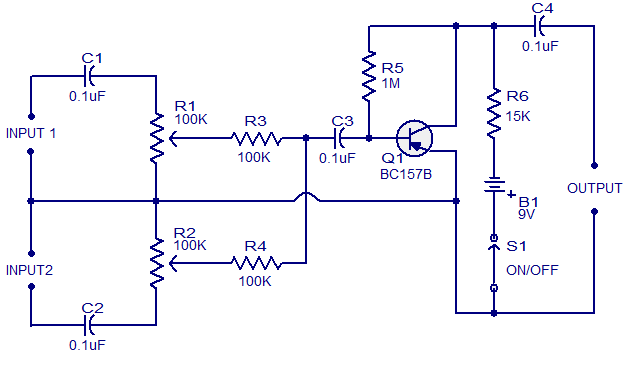
This schematic represents a low-cost microphone mixer that can be assembled using components typically found in a junk box. It is a two-channel microphone mixer designed to accommodate high-impedance dynamic microphones. Transistor Q1 can be any general-purpose PNP transistor,...
This circuit is mainly intended to provide common home stereo amplifiers with a microphone input. Using a stereo microphone the circuit must be doubled. In this case, two separate level controls are better than a dual-ganged stereo potentiometer. Low...
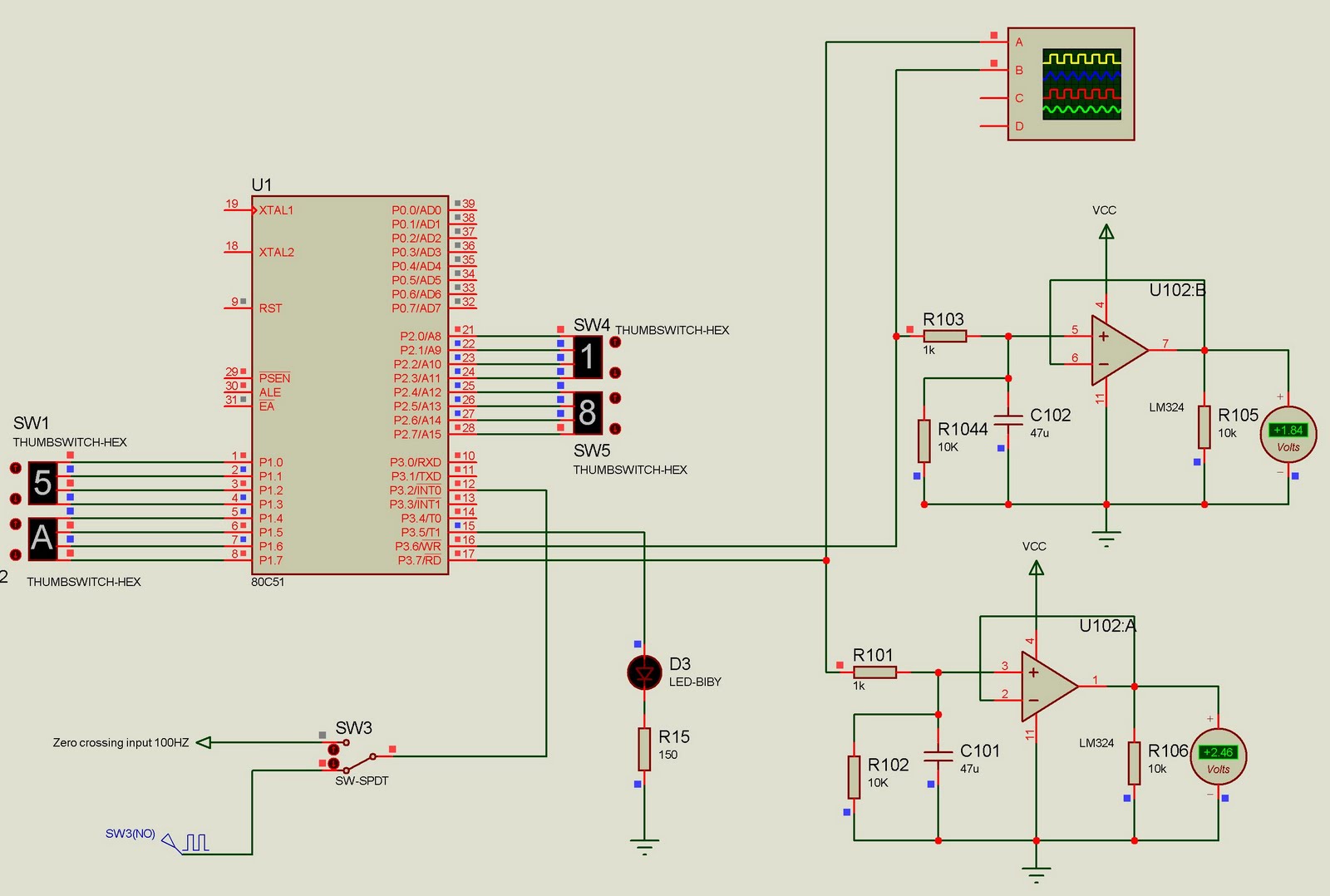
This project currently outputs two PWM signals but can be easily extended to generate multiple PWM signals. The input to the microcontroller consists of 100Hz pulses serving as zero-crossing signals. It is designed for a two-channel DAC, where the...
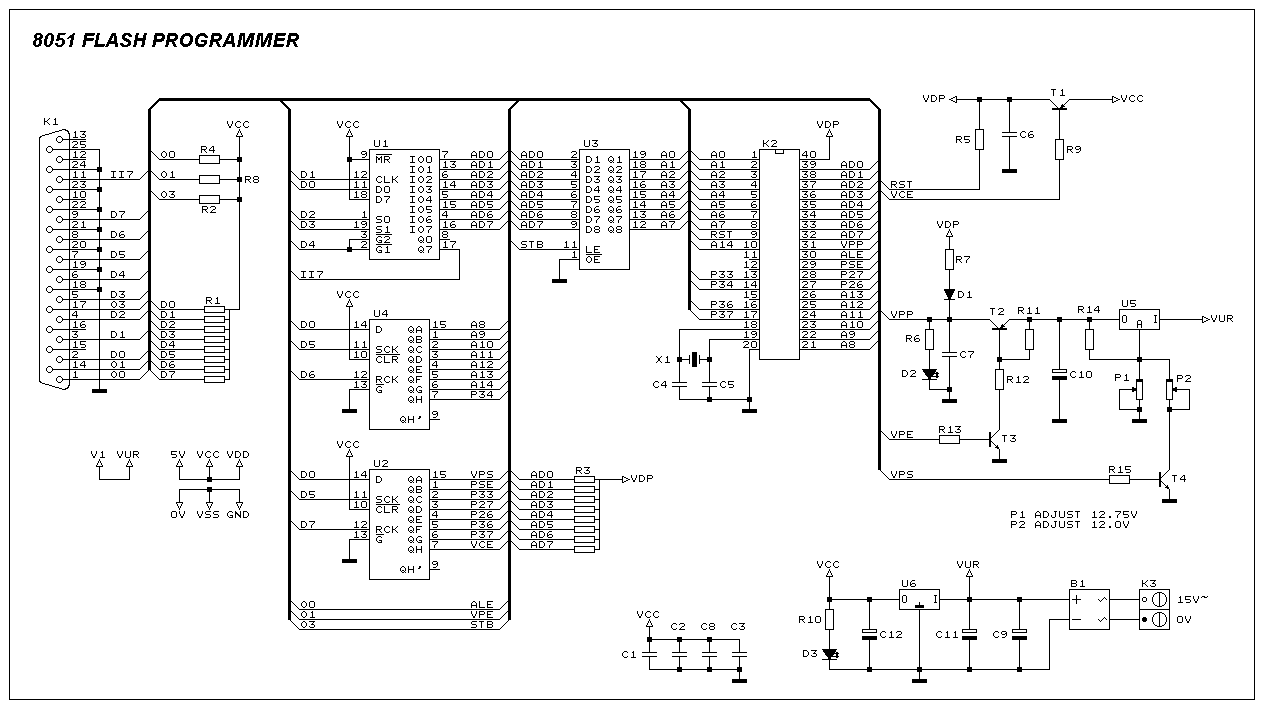
This programmer was designed to be flexible, economical, and easy to build. The programmer hardware utilizes standard TTL series parts, and no special components are used. The programmer is interfaced with the PC parallel port, and there are no...
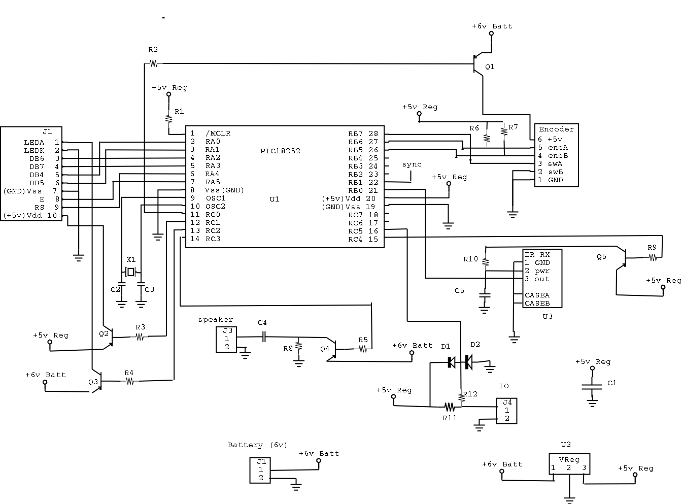
The most significant omission was that the DRUID did not accept confirmation codes (i.e., the solution to the clue) and did not provide directions to the next clue site. Instead, teams had to call in and confirm with Game...
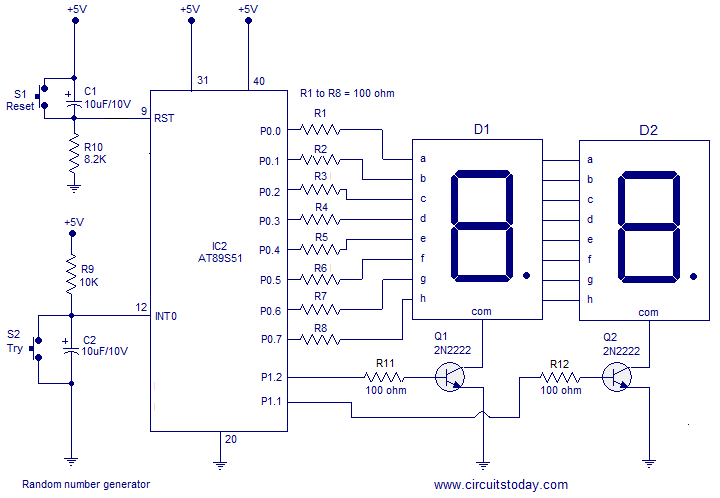
A simple random number generator utilizing the 8051 microcontroller. The AT89S51 is the controller employed in this setup. The circuit design for the random number generator based on the AT89S51 microcontroller involves several essential components and connections. The AT89S51 microcontroller,...
Warning: include(partials/cookie-banner.php): Failed to open stream: Permission denied in /var/www/html/nextgr/view-circuit.php on line 713
Warning: include(): Failed opening 'partials/cookie-banner.php' for inclusion (include_path='.:/usr/share/php') in /var/www/html/nextgr/view-circuit.php on line 713