
Microchip PIC18F252 druid circuit
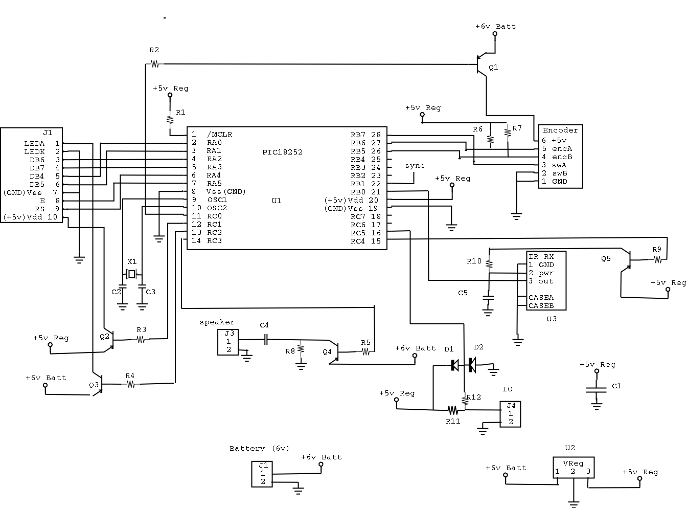
The DRUID circuit design integrates a Microchip PIC18F252 microcontroller, which serves as the central processing unit for the device. This microcontroller is adept at handling various input and output operations, making it suitable for applications requiring real-time processing. The display interface, connected to J1, employs a 4-pin parallel communication protocol where the data is transmitted in 4-bit chunks via the DB4-DB7 pins. The RS pin plays a critical role in distinguishing between control and data commands, ensuring that the microcontroller accurately interprets the intended operations.
The optical rotary encoder mechanism is a pivotal feature of the DRUID, allowing for user interaction through rotational input. The encoder's design, which includes slits on a rotating wheel, ensures precise detection of movement through the use of two LEDs and two phototransistors. This configuration enables the microcontroller to track the position and movement direction of the knob, akin to the functionality found in computer mice.
Power management is a vital aspect of the DRUID's design. The encoder is programmed to enter a low-power state shortly after its last detected movement, significantly extending battery life. The microcontroller's ability to check the encoder at varying intervals, depending on the power state of the device, optimizes power consumption while maintaining responsiveness.
The circuit also includes provisions for backlighting through LEDA and LEDK, enhancing visibility during operation. The design effectively balances functionality with energy efficiency, ensuring that the DRUID remains operational throughout its intended use without compromising performance. This comprehensive approach to circuit design illustrates the intricate considerations involved in developing a robust electronic device.The most glaring ommision was that the DRUID did not accept confirm codes (ie the solution to the clue) and did not give directions to the next cluesite. Instead teams had to call in and confirm with Game Control in order to find out their next destination.
This was due to a lack of planning on my part. The final version of the text including the Confirm and Arrival codes turned out to be about 40KBytes. Since we had about 3K of program, and only 32K of ROM memory total I decided to write a compressor/decompressor to fit all the text in. The compression/decompression software worked, but the decompression was slow and the changes caused instabilities in the software.
I finally had to revert to an earlier version of the software which did not have many of the features that we wanted. At that point there was no time to shrink the messages to fit into 32K and we decided to just abandon the confirm codes and their messages (since the alternative was to not have a working gadget).
On the plus side we built 34 DRUIDS of which 27 actually worked, and during the game not one of them failed. There was one that broke open, but it was still working at the end of the game. I heard that one actually got run over by a van, but I never got that confirmed. The DRUID is based on a Microchip PIC18F252 microcontroller. A microcontroller is basically a small computer on a chip, and they are often used for controlling car engines, appliances, etc.
Below is the circuit diagram. The display is attached to J1. It is controlled with a 4 pin parallel port. The DB4-DB7 pins are the 4 bit data, RS determines whether the data goes to a control register or the data register, and E is toggled to tell the display that the data is valid and should be grabbed off the other pins. LEDA and LEDK are the power for the backlight. The knob on the druid controls an optical rotary encoder. It uses a wheel with slits cut in it in conjunction with 2 LEDs and 2 phottransistors to tell when the encoder rotates.
It works just like a computer mouse (a computer mouse has 2 rotary encoders, one for the X direction and one for the Y direction). The encoder uses a lot of power so I turn it off 1 second after its last movement and only check it once every 10th of a second.
When the DRUID is turned off it only checks the encoder 3 times per second. The 2 signals from the 2 phototransistors are fed into the PIC pins 26 and 27. When the encoder is clicked (pushed in) it connects pin 3 to pin 2. This pulls pin 3 low (0 volts), which pulls the PIC pin 28 low. PIC pin 28 is pulled high by a resistor inside the PIC when the button is not being pressed. 🔗 External reference
Related Circuits
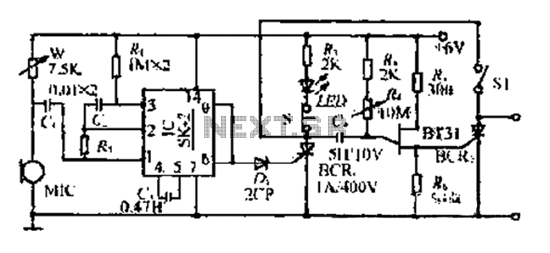
The circuit includes a microphone (MIC) housed in a cylindrical body that captures sound when an object makes contact. The audio signal is coupled to an integrated circuit (IC) for amplification. The output from the IC, at pins 6...

Having reliable connections is essential not only in daily life but also in electronics. Unlike social connections, the dependability of electrical contacts is crucial for the proper functioning of electronic devices. In the realm of electronics, the integrity of electrical...
This circuit provides a visual 9-second delay using 10 LEDs before closing a 12-volt relay. When the reset switch is closed, the 4017 decade counter is reset to the 0 count, illuminating the LED driven from pin 3. The...
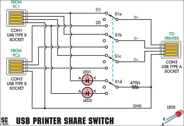
This device enables two computers to share a single USB printer or other USB devices, including external flash drives, memory card readers, or scanners. A rotary switch is used to select the PC that will access the USB device, while...

The CXA1600M and CXA1600P are 8-pin single-chip bipolar integrated circuits (ICs) designed for AM radios. These ICs encompass all necessary functions from the front-end to the power amplifier, eliminating the need for external filters, which makes the attachment of...

This is a simple headphone amplifier circuit designed to drive headphones when a music player lacks sufficient power. The circuit is straightforward and utilizes only three transistors. The first transistor, Q1 (BC 239), along with its associated components, functions...
Warning: include(partials/cookie-banner.php): Failed to open stream: Permission denied in /var/www/html/nextgr/view-circuit.php on line 713
Warning: include(): Failed opening 'partials/cookie-banner.php' for inclusion (include_path='.:/usr/share/php') in /var/www/html/nextgr/view-circuit.php on line 713