
A Repeating Timer Circuit
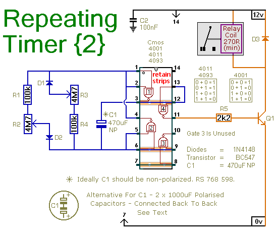
This circuit operates as an asymmetric oscillator, allowing independent control over the relay's energized and de-energized states. The astable oscillator's frequency is influenced by the capacitor C1, which charges and discharges through the resistor network formed by R2 and R3. The adjustable timing is achieved through a combination of fixed resistors (R1 and R4) and variable resistors (R2 and R3), permitting customization of the timing intervals from 1 to 30 minutes.
The relay's operation is critical in applications where timing control is essential. The circuit's design incorporates safety measures, particularly regarding the handling of mains voltage. Users are advised to employ an external relay for high-voltage applications, ensuring safe operation by maintaining adequate distance from low-voltage components.
The use of non-polarized capacitors is essential in this design to prevent damage from incorrect polarity. The back-to-back configuration of two polarized capacitors effectively simulates a non-polarized capacitor, allowing the circuit to function correctly without risk of failure due to capacitor damage. This design choice is particularly useful in environments where non-polarized capacitors may be unavailable.
The circuit is versatile, operating efficiently within a power supply range of 5 to 15 volts, making it adaptable for various applications. The choice of CMOS logic gates provides flexibility in component selection, allowing for the use of alternative gates without compromising functionality.
Overall, this circuit exemplifies a practical approach to timing control in electronic applications, with a focus on safety, adaptability, and ease of construction. Supporting documentation enhances user understanding and facilitates effective implementation of the circuit.This circuit is based on a simple asymmetric oscillator. The length of time the relay remains energized - and the length of time it remains de-energized - are set independently. With the component values shown in the diagram - both periods are adjustable from about 1 to 30 minutes.
The frequency of the Astable Oscillator depends on the value of C1 and the speed at which it charges and discharges through the resistor network. The length of time the relay remains energized is controlled by R2. And the length of the time it remains de-energized is controlled by R3. Owing to manufacturing tolerances - the precise length of the time periods available depends on the characteristics of the actual components you`ve used. R1 & R4 set the minimum period lengths at about 1-minute - while R2 & R3 set the maximum periods at about 30-minutes.
You can choose component values that suit your own requirements. If your time periods don`t need to be too precise - and more-or-less is close enough - you can leave out the pots altogether - and simply rely on R1 & R4 to set the times. Do not use the "on-board" relay to switch mains voltage. The board`s layout does not offer sufficient isolation between the relay contacts and the low-voltage components.
If you want to switch mains voltage - mount a suitably rated relay somewhere safe - Away From The Board. I`ve used a SPCO/SPDT relay - but you can use a multi-pole relay if it suits your application. A regular electrolytic capacitor is polarised. If the charge on its plates is the wrong way round - DC current will flow through the capacitor. If the current is high enough - the capacitor will heat up and explode. When the oscillator is running - the polarity of the charge on C1 keeps reversing. So C1 needs to be non-polarised. However - you can simulate a non-polarised 470uF capacitor by connecting two 1000uF polarised capacitors back to back - as shown.
How and why this works is explained in the Detailed Circuit Because non-polarised capacitors aren`t widely available - the prototype was built using two polarised capacitors. The timer is designed for a 12-volt power supply. However - it will work at anything from 5 to 15-volts. All you need do is select a relay to suit your supply voltage. The Cmos gates are being used as simple inverters. So - although I`ve used a Cmos 4093 in the circuit diagram - a Cmos 4001 or Cmos 4011 will work just as well.
The Support Material for this circuit includes a step-by-step guide to the construction of the circuit-board - a parts list - a detailed circuit description - and more. 🔗 External reference
Related Circuits
Hello everyone, I am not well-versed in electronics, so I would appreciate it if someone could create a diagram for me. I would like to modify a circuit so that it can dial a number using speed dial and...
The regenerative effect of a 4-quadrant inverter necessitates power dissipation in some form. In large industrial drives, this power is typically re-inverted back onto the national grid. However, for smaller applications, implementing a braking circuit is advisable. For low-power...
The receiver circuit and display module will receive the high-frequency AC power cord and decode it to provide actual temperature readings using digital IC No. CD4553 (Three-digit BCD Counter IC) and IC CD4511 (BCD-to-7-Segment Latch/Decoder/Driver IC). The frequency pulses...
This Korean SuperCap OEM supports usage in series configurations. Consider whether the implementation will be manual or automatic, such as with a smart battery charger or a power fail backup circuit. It is essential to balance the voltage and...
This precise one-pulse-per-second clock is constructed using a few common components and is driven by a 50 or 60 Hertz mains supply without a direct connection to it. An audible beep or a metronome-like click, along with a visible...
This project involves a straightforward and practical 12V power supply circuit utilizing the LM7812 integrated circuit (IC). The LM7812 is a three-terminal fixed voltage regulator IC housed in a TO-220 package. It incorporates several built-in features such as thermal...
Warning: include(partials/cookie-banner.php): Failed to open stream: Permission denied in /var/www/html/nextgr/view-circuit.php on line 713
Warning: include(): Failed opening 'partials/cookie-banner.php' for inclusion (include_path='.:/usr/share/php') in /var/www/html/nextgr/view-circuit.php on line 713