
Video circuits
The schematic design incorporates various components that work together to facilitate the display of a monochrome video image on the oscilloscope tube. The synchronization and deflection IC (LA7801) plays a central role in generating the necessary timing signals for horizontal and vertical sweeps. The integration of FETs for resetting the integrators ensures that the sawtooth waveforms are produced accurately, which is critical for maintaining the integrity of the video signal being displayed.
The feedback mechanism involving the ECC81 valve and operational amplifiers is crucial for stabilizing the output and enhancing the linearity of the deflection system. This is particularly important given the high voltage requirements of the RCA tube, which necessitates careful management of the output to prevent distortion in the displayed image. The use of potentiometers for adjusting picture size and position allows for fine-tuning of the display, accommodating variations in the input signal and user preferences.
In conclusion, the described circuit is a sophisticated integration of various electronic components, designed to achieve the goal of displaying a monochrome video image on an oscilloscope tube. The careful selection of parts, attention to timing and synchronization, and the implementation of feedback mechanisms are all critical elements that contribute to the successful operation of this electronic system.This page describes the development of electronics to display a monochrome video image on an electrostatic oscilloscope tube. This work is complementary to the Electron Optics page in the Experiments section. The ultimate goal is to display a moving video picture on a completely home made cathode ray gun inside the bell jar of a vacuum rig.
For th is reason I chose to use a 1950`s RCA 3RP1-A oscilloscope tube. It is very similar in specification to my homemade electron gun and so is well suited to the development of the electronics. It should ultimately be possible to disconnect the RCA tube and connect the homemade one. The circuit is designed for use with a PAL composite video signal, but it should be possible to adapt it for use with NTSC or SECAM by changing a few component values.
In particular, the ramp rates of the sweep integrators may need to be adjusted slightly. I chose to use a Sanyo LA7801 synchronization and deflection IC. This was the most suitable part in my bits box for which I could obtain a data sheet. This part is obsolete but could probably be obtained from an old television. Other timebase ICs could be used with appropriate alteration of the circuit. The circuit is closely based upon that provided in the data sheet. Click on the schematic below to see it in higher resolution. The line pulse output at pin 4 of the LA7801 consists of a 2V, 25us long positive rectangular pulse. The rising edge coincides with the start of the line. The field pulse output at pin 6 consists of a 3V, 1. 5ms long positive rectangular pulse which coincides with the field blanking period. The integrators (below) ramp freely until reset by the FETs (TR1 and TR2). This gives the required `saw tooth` sweep waveforms. One PAL line lasts 64us, so the horizontal integrator ramps to 9. 6V before resetting. A field (there are two fields to a frame) lasts 20ms, so the vertical integrator ramps to 9. 4V before resetting. Potentiometers R23 and R28 set the horizontal and vertical picture size. The oscillograph below shows the operation of the horizontal scan integrator. The probes used were x10. From top to bottom, the traces are IC1 pin 4 (2V / division), TR1 gate (5V / division), IC3 pin 6 (10V / division) and the video signal at IC301 pin 6 (1V / division). The video amplifier is described later. The square pulses in the video waveform are the line synchronization pulses and are extracted by the sync separator in the timebase (IC1) to lock the horizontal sweep.
The RCA tube has a vertical deflection factor of 52 to 70V per inch per kV of accelerating voltage, so a high voltage drive is required. An ECC81 double triode valve was chosen for the high voltage output. Operational amplifiers in the feedback improve the linearity and set the voltage gain. Click on the schematic below to see it in higher resolution. R105 and R104 provides the feedback from valve V101a. The anode voltage is divided by 19 and fed back to the op-amp. R101, R102 and R103 set the inputs of op-amp IC101A to around 5. 3V. Thus the anode voltage is set to about 100V (half the HT voltage). Potentiometer R103 adjusts the horizontal picture position. D101 protects the op-amp. C102 and C104 are for high frequency stability. IC101B and associated resistors invert the input signal and apply it to a second valve output stage comprising V101b and IC101D.
The horizontal deflection plates are connected to the valve anodes and are driven in bridge mode. This provides a differential drive of almost 400V peak to peak from a 200V supply. IC101C is not used. An ECC81 double triode is again used for the high voltage output. The bandwidth of the LM348 op-amp used in the vertical amplifier proved to be inadequate for the horizontal amplifier and so it was replaced by an LF347. The LF347 has adequate bandwidth and I happened to have some in my bits box. Click on the schematic below to see it in higher resolution. The values of C 🔗 External reference
Related Circuits
Here is the schematic diagram for a 20 Watt driver. I developed this circuit in 1985, and used it to build a lamp that found much use both as camping light and as emergency light during the then-frequent power...
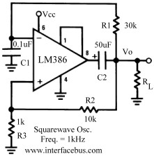
Several operational amplifier circuits are presented here, configured as square wave oscillators. A square wave is a periodic pulse train with a 50 percent duty cycle. The operational amplifier functions as a high-gain amplifier, and oscillation is achieved with...
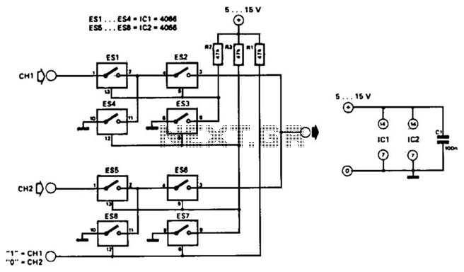
This combination sync stripper and universal video interface can solve various problems, including interfacing Super Nintendo with other devices, video overlay, and locking TV frames for scopes. Kits, fully tested units, and custom cable assemblies are available through Redmond...

Transistors are essential components of electronic circuits. The success of a circuit design depends on the selection of the appropriate transistor type and the calculations involved. Transistors serve as fundamental building blocks in electronic circuits, playing critical roles in amplification,...
This section provides details for generating a composite video output signal from a camera to drive an external monitor. The circuit, designed by Peter Smith, integrates a DC-restorer, a switchable gamma corrector, and a video/sync mixer using a photodiode...
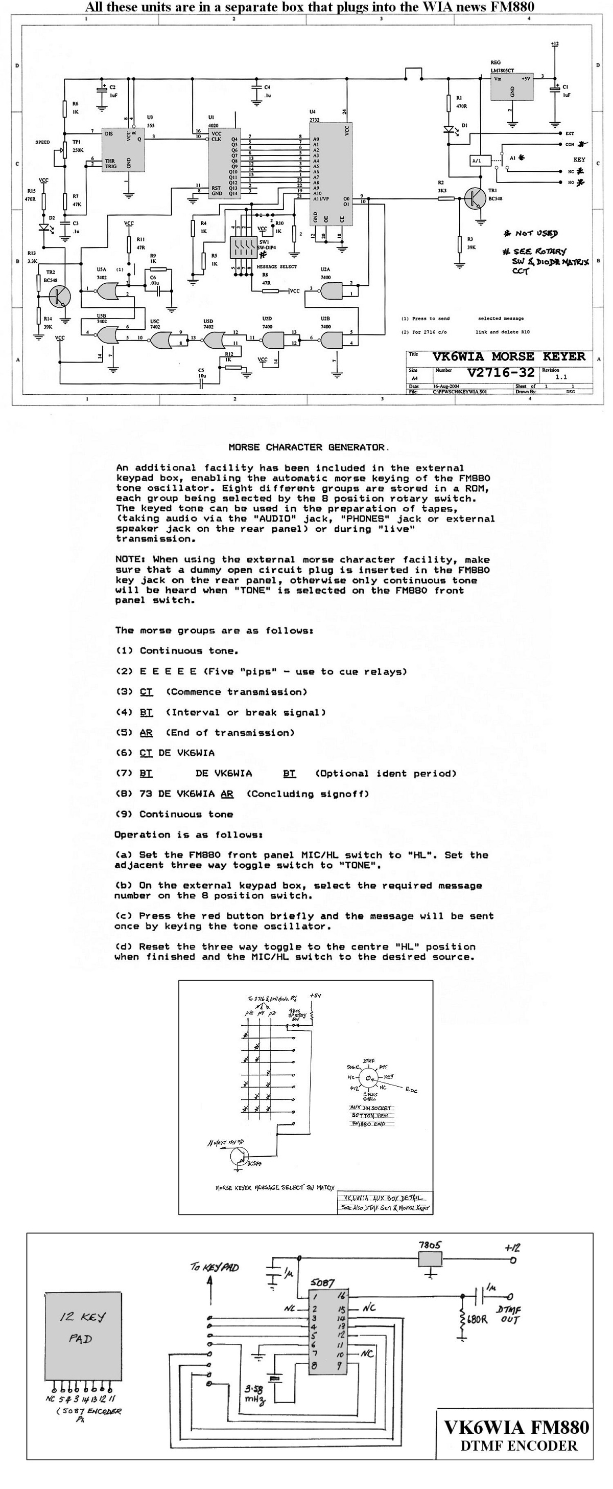
The unit is based on a PHILIPS FM880 link transceiver originally supplied to a Telecom Australia specification for telephone applications in remote areas of Australia. The FM880 is part of a family of equipment that includes the PHILIPS FM828/FM814...