
A simple bedside lamp delay circuit

The described circuit employs a bistable multivibrator configuration, utilizing integrated circuits (ICs) and discrete components to achieve stable switching behavior. The Ge transistor serves as a key element in the circuit, allowing for reliable operation within the designated parameters. The inclusion of a thyristor power module enhances the circuit's ability to manage higher power loads, making it suitable for applications requiring robust performance.
The one-shot delay feature is particularly beneficial for timing applications, where a precise delay is necessary before initiating an action. This is achieved through careful component selection and configuration, ensuring that the timing interval can be adjusted as needed. The zero-trigger circuit plays a critical role in ensuring that the thyristor is activated only under specific conditions, preventing unwanted triggering and enhancing the circuit's reliability.
The RF electricity conversion aspect highlights the circuit's versatility, allowing it to be integrated into systems that utilize radio frequency signals. The diode and voltage rectifier work together to ensure that the output is a stable 6V DC, which is essential for powering the timing control circuit effectively. This stable voltage is crucial for the operation of the nozzle barrier circuit, ensuring that it functions correctly and consistently.
Furthermore, the use of silicon-controlled rectifiers (SCRs) allows for efficient control of low-current applications, providing a means to manage current flow with precision. The design emphasizes rigorous screening processes to ensure that the components selected meet the necessary specifications for reliable operation. Overall, the circuit's comprehensive design and component integration make it suitable for a range of electronic applications requiring precise timing and control.FIG IC, ICR, Ri, R ,. AN composition and bistable contact cast Ge circuit. ICc. lc world where;, c2, Dj New Zealand into one-shot delay circuit meaning: [CL. ICrr W well-linkin g JH, this team can be enhanced driving gourd plant play: Cave said G b obituary I composed of thyristor power m, spit zero trigger circuit. rf electricity by 1001 (D. n resistance voltage rectifier .D t steady f wool C;. Hao waves to provide a stable DC 6V for the timing control circuit for the nozzle i barrier circuit subtotal J Wu devices trained Neighborhoods low, add SCR not like the generous circuit ql a rigorous screening small current through the two-way contact marrow purpose SCI 1 are bite often used
Related Circuits
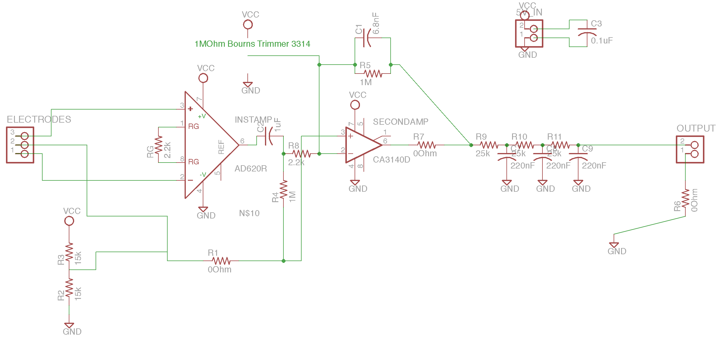
The circuit is based on the designs of Chipstein and Cornell, utilizing an instrumentation amplifier (AD620) to measure the voltage difference between two locations on the body. A second amplifier (CA3140) further amplifies this differential signal. A potentiometer is...
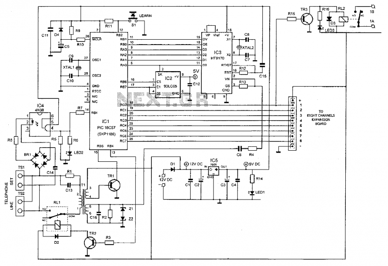
This device enables remote control of various appliances (up to eight with suitable add-on expansion boards) such as lights, water heaters, air conditioning, plant watering systems, alarms, etc., via a relay. It allows users to perform actions such as...

Simple AC to DC converter 9VAC to 35VDC. This is a basic example of an AC to DC converter model designed to be straightforward. It modifies 9VAC input to produce 35VDC output, depending on various factors. The AC to DC...

Involvement is a modified version of the classic circuit of automatic level control signal used in tape recorders. The purchase price of the components (using TL072) does not exceed CZK 60 for a channel. For a range of entry...

The circuit illustrated in the schematic diagram below allows for the visualization of the direction and shaft rotation of a stepper motor on an LED display. Instead of employing a digital rotation encoder as an input, this circuit utilizes...
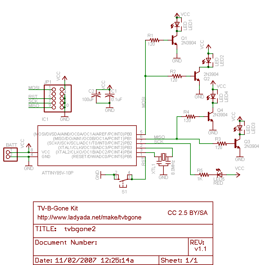
Why use one resistor and one transistor for each LED instead of connecting the LEDs in series and controlling them with a single transistor? This approach is controlled by an Arduino pin through a single resistor. While there is...