
A Simple but Good Battery Charger
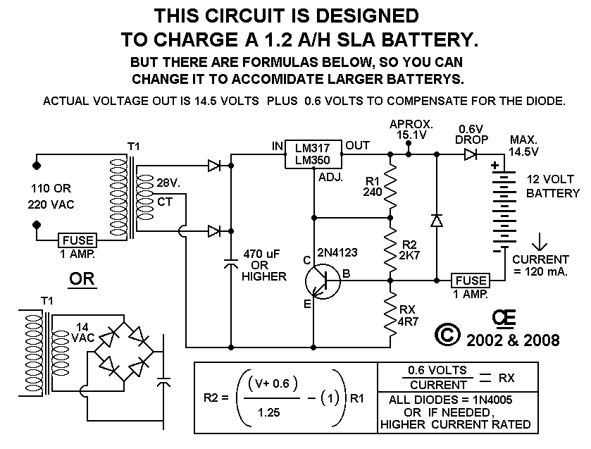
The described circuit is designed for efficient charging of Gel Cell and SLA batteries, which are commonly used in various portable electronic devices, including metal detectors. The circuit can be configured to handle different battery capacities, specifically accommodating those rated up to 10 A/H, making it versatile for various applications.
The charging circuit typically employs a voltage regulator or a dedicated battery management IC to ensure that the charging voltage and current remain within safe limits for the battery type. The circuit may include features such as over-voltage protection, over-current protection, and temperature monitoring to enhance safety and efficiency during the charging process.
To modify the circuit for higher current batteries, adjustments can be made to the current limiting resistors and the specifications of the components used, such as the transformer or switching regulator, to ensure they can handle the increased current without overheating or failing.
Additionally, the circuit may include indicators such as LEDs to display the charging status, providing visual feedback to the user. Proper layout considerations should be taken into account to minimize resistance and inductance in the circuit, which can affect charging efficiency.
Overall, this charging circuit is a robust solution for powering Gel Cell and SLA batteries, ensuring reliable performance in applications such as metal detectors and other electronic devices requiring portable power sources.Using this circuit will give Good Charging results to a Gell Cell or SLA type Batterys as used in my Metal Detector project. And it can be modified to accomidate higher current batterys. It is Probably quite Suitable for up to a 10 A/H Rating 🔗 External reference
Related Circuits
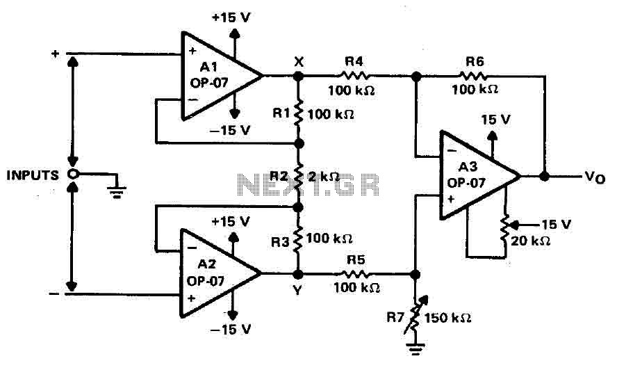
Operational amplifiers A1 and A2 are connected in a non-inverting configuration to form amplifier A3. The operational amplifier A3 can be classified as a subtractor circuit that converts the differential signal between the floating points X and Y into...
This is the first oscillator that was built. Various resources such as books, magazines, and online schematics were reviewed. Most of the designs encountered were either Colpitts or Hartley oscillators. While these designs are relatively straightforward, they require specific...
Certain circumstances and areas require the detection and securing of entrance paths through alarm systems, ensuring that whenever an individual opens an entrance door, the situation is instantly monitored by triggering an alarm. Battery-operated window and door alarms are...
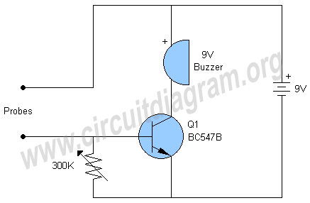
This is a straightforward water level buzzer circuit designed to detect the water level in tanks, pools, washing machines, and similar applications. The circuit features two probes that, upon contact with water, trigger the buzzer to emit a sound....
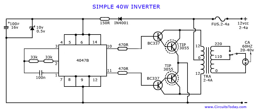
An article on how to create an inverter using a simple 40-watt inverter circuit diagram and schematics. This inverter converts 12 volts to 220 volts using the CD4047 integrated circuit. The described inverter circuit utilizes the CD4047 IC, which is...
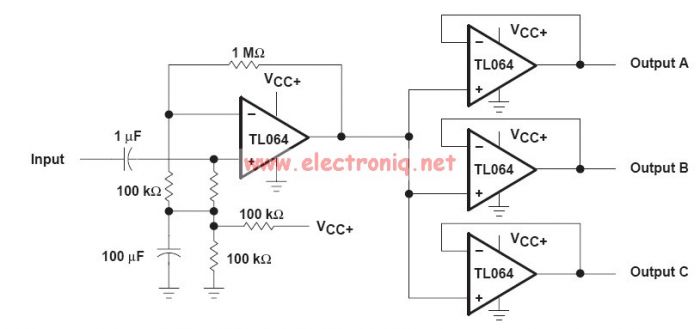
This audio distribution electronic project circuit diagram is designed using the TL064 or TL06 operational amplifiers and some other common electronic parts. The audio distribution circuit utilizes TL064 or TL06 operational amplifiers, which are quad op-amps known for their low...