
Simple differential amplifier circuit

The potentiometer can be adjusted to optimize common-mode rejection. Input amplifiers A1 and A2 provide some differential gain; however, the common-mode input voltage experiences unity gain. These voltages do not manifest as differential signals at the input of amplifier A3 because they are canceled when they appear at equal levels across the R2 resistor. This type of low-level differential amplifier is widely utilized in signal processing applications. It is particularly beneficial for low-frequency signals, typically sourced from sensors or thermocouples, which are amplified and transmitted in a balanced mode. The amplifier is powered by supplies of ±15 V, which is necessary to ensure zero input offset voltage at the output of amplifier A3.
Operational amplifiers A1 and A2 serve as the initial differential amplifiers in this configuration, where they amplify the difference between the input signals while rejecting common-mode signals. The non-inverting configuration allows for a straightforward implementation, providing a robust means of signal processing. The output from amplifier A3 is a single-ended voltage that represents the differential input, making it suitable for interfacing with further stages of processing or measurement systems.
The choice of resistors R4, R5, R6, and R7 is critical in determining the performance characteristics of the amplifier, particularly in terms of gain and common-mode rejection. The use of high-precision resistors minimizes the impact of resistor tolerances on the performance, thus enhancing the overall accuracy of the circuit. The introduction of a potentiometer for R7 allows for fine-tuning of the common-mode rejection ratio, accommodating variations in the input signal or environmental conditions.
This amplifier configuration is particularly advantageous in applications where low-level signals need to be accurately measured and processed, such as in medical instrumentation, industrial sensors, and data acquisition systems. The ability to reject common-mode noise is essential in these applications, ensuring that the output signal is a true representation of the differential input. The ±15 V power supply provides the necessary headroom for the operational amplifiers to function effectively, allowing for a wide dynamic range and improved linearity in the output signal.Operational amplifiers Al and A2 are connected in a noninverting configuration of their training sorties amplifier A3. The operational amplifier A3-one could call a subtractor circuit that converts the differential signal between the floating point X and Y in a single ended output voltage .
Although not mandatory, amplifier A3 is usually used in unity gain and R4, R5, R6, and R7 are all equal. Joining-rejection of the amplifier A3 is a function of how the rate of R4: R5 R6 is the ratio: R7. For example, when using resistors with a tolerance of 0.1%, common mode rejection exceeds 60 dB. further improvement can be achieved by using a potentiometer (slightly higher than the value of R6) to R7.
The potentiometer can be adjusted for best common mode rejection. Input amplifiers Al and A2 will be some differential gain, but the common mode input voltage will gain experience unit. These tensions do not appear as differential signals to the input of amplifier A3, because when they appear at equal levels at both ends of R2-resistance, they are canceled.
This type differential amplifier oflow level is widely used in signal processing. It is also useful for low frequency signals and routinely received from a sensor or thermocouple output. which are amplified and transmitted in a balanced mode. The amplifier is powered by supplies V ± 15. It is only necessary for zero input offset voltage of the output amplifier A3.
Related Circuits
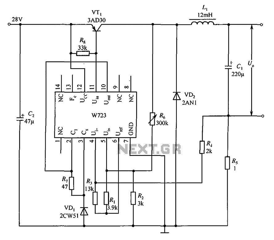
The Multiport W723 is an adjustable constant current regulator designed for use in switching regulator circuits, capable of delivering an output current of 1A. In the illustrated circuit, the W723 reference base voltage is approximately 7.2V. This voltage is...

The physical circuit layout is extremely critical. Breadboarding is not recommended. A double-sided copper-clad printed circuit board will result in more favorable system operation. The design and implementation of electronic circuits require careful consideration of the physical layout, as it...
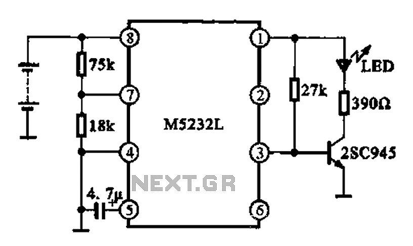
A battery voltage indication circuit that changes the status display. When the battery voltage is normal, an additional transistor drives an LED, which remains off. However, if the battery voltage falls below a critical threshold, the LED begins to...
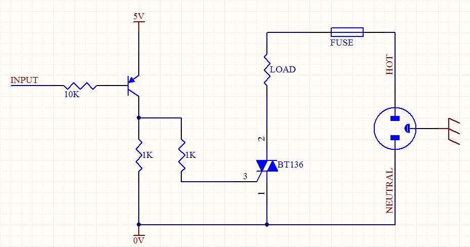
A circuit was designed to function as a light dimmer, utilizing a BT136 SCR and an MOC3022 optocoupler. However, the circuit did not operate as intended. The circuit aims to control the brightness of a light source through phase control...
This circuit is similar to the previous one but employs positive feedback to enhance the amplitude delivered to the speaker. It was adapted from a small five-transistor radio that utilizes a 25-ohm speaker. In the prior circuit, the load...
The circuit is depicted. It is capable of both manual and automatic control. The circuit in question is designed to facilitate dual modes of operation: manual and automatic control. This versatility allows users to engage with the system according to...